14
PWDXXA-40X_20 5715-677 UK.indd 26.01.17
Electronic for proportional DC valves
Series PWDXXA-40X
Operation Manual
Parker Hannifin Corporation
Hydraulics Group
Parker Hannifin Corporation
Hydraulics Group
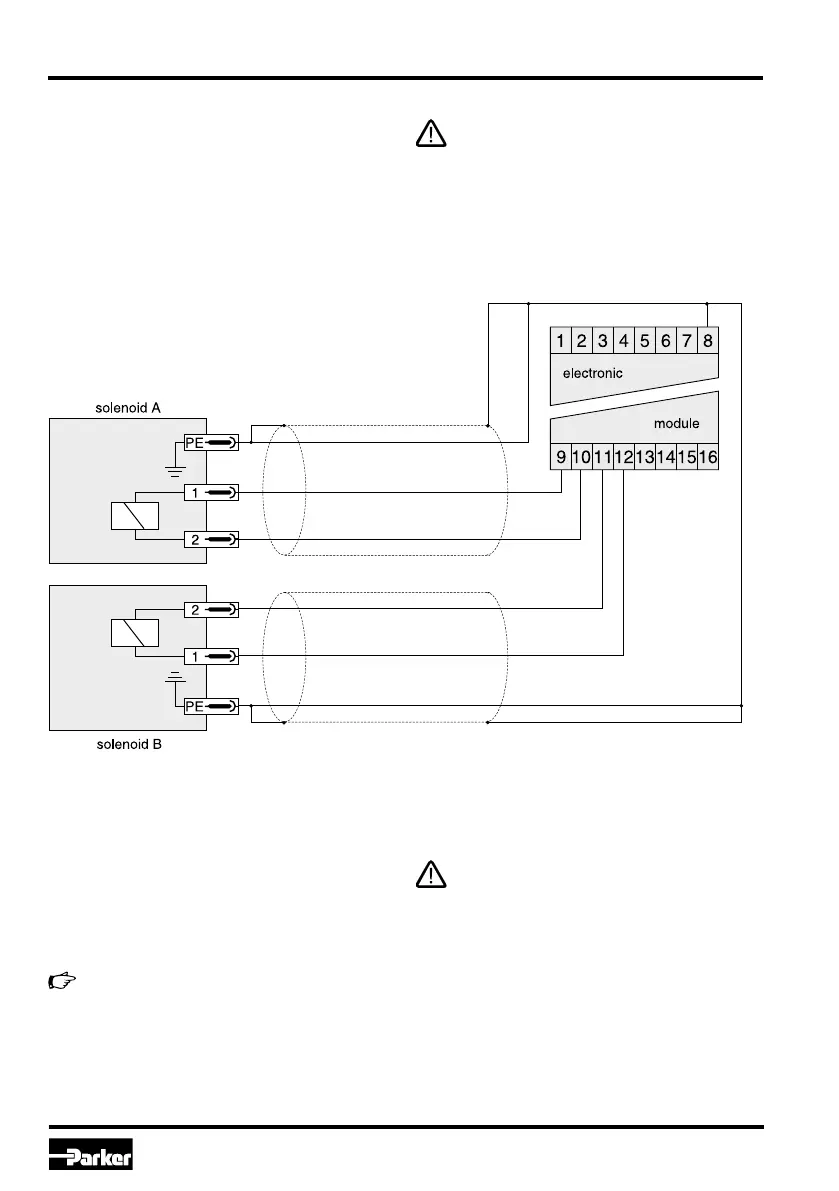
Wiring diagram of solenoid output
Solenoid outputs
The valve solenoids have to be connected to the
terminals 9 and 10 as well as 11 and 12, while the
earth ground connection of the solenoids is made
via terminal 8. The connection has to be shielded.
The solenoid connectors may not contain any
protective or indication components, i.e. re-
covery diodes or lamps, otherwise function
disturbances and permanent damages may
occur to the electronics module.
Sensor input
The sensor has to be wired to the terminals 13...16,
the earth ground connection will be made via ter-
minal 8. The connection has to be shielded. The
sensor type is selectable via software parameter
E11.
The module is usable for valves of design
series D*FS, RLL*R, WLL*R (standard con-
nection). On appropriate selection of the
parameter E11, sensors with other signal
spans may be connected.
Connection of an unusable sensor may lead
to permanent damage to the electronics
module.
 Loading...