24
PWDXXA-40X_20 5715-677 UK.indd 26.01.17
Electronic for proportional DC valves
Series PWDXXA-40X
Operation Manual
Parker Hannifin Corporation
Hydraulics Group
Parker Hannifin Corporation
Hydraulics Group
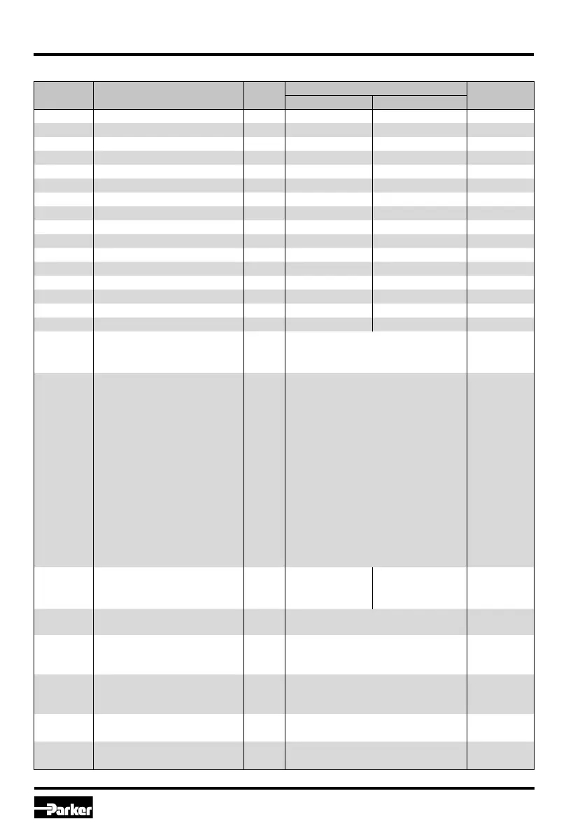
Parameter overview for expert mode
Parameter Description Unit
Parameter range
Default
setting
from up to
P5 dither amplitude % 0 10.0 0
P6 dither frequncy Hz 0 300 0
P9 quiescent current channel A % 0 25.0 0
P10 quiescent current channel B % 0 25.0 0
P13 bypass gain
–
0 100.0 0
P14 T-portion PT1-element
–
0 100.0 0
P16 P-portion
–
0 100.0 0
P17 I-portion
–
0 100.0 0
P18 D-portion
–
-100.0 +100.0 0
P19 T-portion DT1-element
–
0 100.0 0
P20 feedback scaling % 0 200.0 100.0
P21 comparator function window % 0 200.0 0
P23 comparator rise delay time ms 0 10000 0
P24 comparator turn-off delay time ms 0 10000 0
P26 window I-portion - 0 200.0 20.0
P27 reduct. window I-portion - 0 100.0 100.0
E2 closed loop control
–
0 = inactive (open loop)
0 = inaktiv1 = active (int. closed loop)
2 = active (ext. closed loop)
E11 position transducer type
–
1 = ±10 V
1 = ±10 V
2 = ±20 mA
3 = 4-20 mA bipolar
4 = D1FC/WLL NG06
5 = D3FC/WLL NG10
6 = RLL NG06
7 = D31FS
8 = D41FS
9 = D81FS
10 = D91FS
11 = D111FS
12 = 4-20 mA unipolar
13 = TEL 50/70
14 = TEL 90/125
E12
cable break detection
feedback
–
0
voltage: 0
0 = voltagecurrent ±20 mA: 0
current 4-20 mA: 1
E25 MIN operating threshold
–
0 = 1 %
1 = 0.01 %
0 = 1 %
IA solenoid current channel A
–
1 = 3.5 A
2 = 2.7 A
4 = 1.3 A
4 = 1.3 A
IB solenoid current channel B
–
1 = 3.5 A
2 = 2.7 A
4 = 1.3 A
4 = 1.3 A
J2 Compability mode –
0 = off (fast)
0 = off
1 = on (Design <20)
E81
Function
–
0 = Sensor supply
0
"Sensor supply" pin 1 = Comparator out

 Loading...


