23
Electronic for proportional DC valves
Series PWDXXA-40X
Operation Manual
PWDXXA-40X_20 5715-677 UK.indd 26.01.17
Parker Hannifin Corporation
Hydraulics Group
Parker Hannifin Corporation
Hydraulics Group
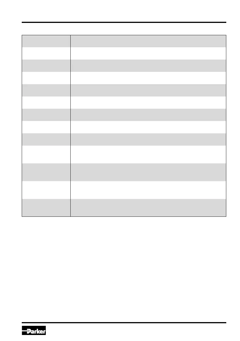
S5
ramp accel. channel A
Adjustment of ramp rate for increasing of valve side A.
To avoid switching noise.
S6
ramp decel. channel A
Adjustment of ramp rate for decreasing of valve side A.
To avoid switching noise.
S7
ramp accel. channel B
Adjustment of ramp rate for decreasing of valve side B.
To avoid switching noise.
S8
ramp decel. channel B
Adjustment of ramp rate for decreasing of valve side B.
To avoid switching noise.
P1
offset
Adjustment of zero position shifting (offset).
To compensate for unbalances within the zero position of the valve.
P3
MAX channel A
Adjustment of maximum stroke for valve side A at 100 % command signal.
To match the command signal span to the valve operating range.
P4
MAX channel B
Adjustment of maximum stroke for valve side B at 100 % command signal.
To match the command signal span to the valve operating range.
P7
MIN channel A
Adjustment of stroke step for valve side A at 0,1 % command signal.
To compensate for the overlap of the valve spool.
P8
MIN channel B
Adjustment of stroke step for valve side B at 0,1 % command signal.
To compensate for the overlap of the valve spool.
P11
command signal
polarity
Adjustment of the command signal polarity.
To match the command signal polarity to the valve operating direction.
P12
feedback signal
polarity
Adjustment of the feedback signal polarity.
To match the sensor signal polarity to the solenoid polarity of the valve.
E17
type of com.
signal device
Adjustment of the command signal option.
To match the command signal input to the input signal mode.
E19
cable break detection
command
Adjustment of the operating mode for the command cable break detection.
To turn on resp. off the cable break detection for the command signal at a
selected command signal option of 4...20 mA.
Individual description of basic parameters
 Loading...