Part A: SciPres
®
Pressure Sensor Hardware
1.0 Overview
The SciLog
®
SciPres
®
pressure sensor system consists of two major components, the SciPres
®
pressure monitor, with its power supply, and the single-use SciPres
®
pressure sensor, with its cable.
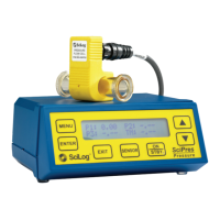
The monitor is a small desktop package with a backlit display and seven buttons for easy interface and
menu selections. It displays up to three measured pressures and one calculated pressure in real time.
The monitor’s output signals are in both analog and digital forms. It comes with a small wall adapter
as a universal power supply.
The monitor reads and utilizes calibration data from SciPres
®
sensors that have been calibrated to two
points, 0 and 30 psi, or three points, 0, 54 and 6 psi depending upon the sensor purchased. It has also
been equipped with a Supervisor Password, a Max Pressure Watchdog, and a Noise Filter setting.
The “Max Pressure Watchdog” feature records in the sensor’s memory the maximum pressure seen
by the sensor while it is connected to the SciPres
®
Monitor. This value is displayed for a few seconds
along with the Sensor ID and calibration information when the Monitor is powered up after a sensor is
connected.
The Filter setting is used to average the pressure signals when peristaltic pump heads are used. This
makes the display readings easier to interpret, and produces cleaner graphs that are easier to read. At
the lowest setting, the data is “live”, and at the highest, it is averaged over a four second period.
The SciPres
®
pressure sensors utilize a silicone piezoresisitive sensing element in a polysulphone tube
available in five sizes: Luer,
3
/
8
" or
1
/
2
" Barb,
3
/
4
" and 1" ‘Ladish’ Sanitary TC connections.
All sensors are pre-calibrated at the factory, and retain the calibration data on a small chip embedded
in the sensor body. The following information is retained and is accessed upon connection to the
sensor:
• ID number (Contains Size, Lot number, Mfr Code, and Calibration date)
• Calibration Factors
• Calibration Points
• Pressure Zero Offset
• Max Pressure Value
Caution: Disconnection and reconnection of the sensor while in operation may cause
corruption of the sensor’s memorys and consequent loss of calibration. Please turn the
monitor off when connecting / disconnecting the sensors.
11
Note: The maximum recommended pressure for the sensors is 60 psi (4.14 bar). If this is
exceeded, problems with leakage and functionality can occur.
 Loading...