Technical Data
Electronic
module
prop. valve with
one solenoid
Design
series
(not required
for ordering)
Module type
Amplifier,
adjustable
min./max. limits
accel.-/decel.-ramp
2 x 2 internal pro-
grammable
commands
Variable
solenoid
current
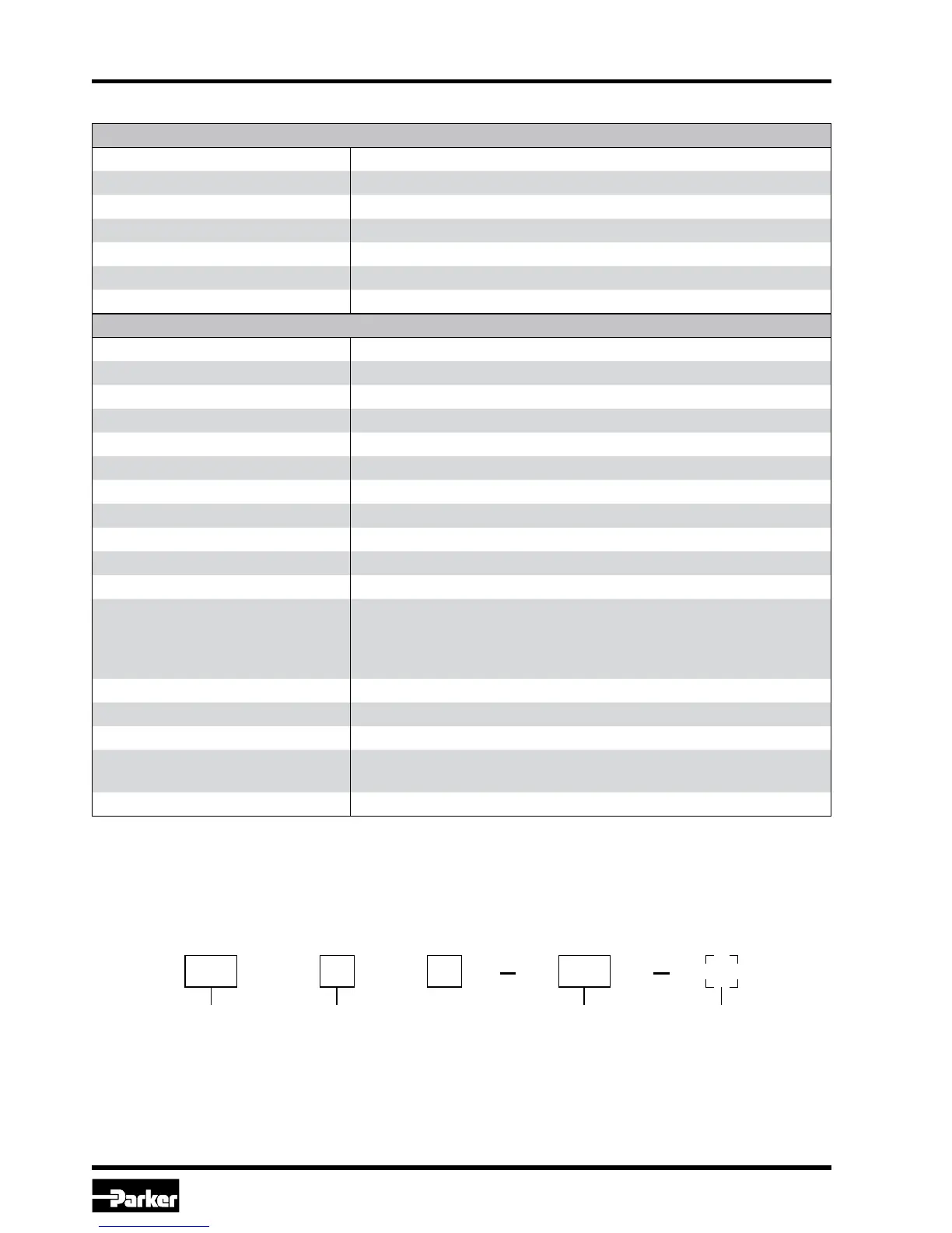
Ordering Code
General
Model Module package for snap-on mounting on EN 50022 rail
Package material Polycarbonate
Inflammability class V0 acc. UL 94
Installation position Any
Ambient temperature range [°C] -20...+60
Protection class NEMA 1/IP20 acc. EN 60529
Weight [g] 160
Electrical
Duty ratio [%] 100
Supply voltage [VDC] 18...30, ripple < 5 % eff., surge free *)
Switch-on current typ. [A] 22 for 0.2 mS
Current consumption max. [A] 5.0
Pre-fusing [A] 6.3 A medium lag
Command signal [V] 0...+10, ripple < 0.01 % eff., surge free, Ri = 150 kOhm
Input signal resolution [%] 0,025
Differential input voltage max. [V] 30 for terminals 5 und 6 against PE (terminal 8)
Enable signal [V] 0...4.0: Off / 9.0...30: On / Ri = 30 kOhm
Channel recall signal [V] 0...4.0: Off / 9.0...30: On / Ri = 30 kOhm
Status signal [V] 0...0.5: Off / Us: On / rated max. 15 mA
Adjustment ranges Min
Max
Ramp
Current
[%]
[%]
[s]
[A]
0...50
50...100
0...32.5
0.8/1.3/1.8/2.7/3.5
Interface RS232C, DSub 9p. male for null modem cable
EMC EN 50081-2, EN 50082-2
Connection Screw terminals 0.2...2.5 mm², disconnectable
Cable specification
[AWG]
[AWG]
16 overall braid shield for supply voltage and solenoids
20 overall braid shield for sensor and signal
Cable length [m] 50
*)
If solenoids with a nominal voltage of 24 V are connected, the supply voltage has to be raised to 29 V.
00PCD A 400
 Loading...