Bulletin 76-00 B
2
High
Pressure
Receiver
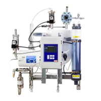
Evaporative
Condensers
Auto Purger
(Model V300)
High Pressure
Liquid Main
Suction
Line
Liquid
Refrigerant
Line
Gas
Refrigerant
Line
Foul
Gas
Line
P
P
P
P
P
Table of Contents
Technical Data ...............................................2
Introduction .................................................2
Purge Cycle. . . . . . . . . . . . . . . . . . . . . . . . . . . . . . . . . . . . . . . . . . . . . . . . . . 3
Installation ..................................................4
Startup Instructions ..........................................7
Nameplate Information ......................................7
Password Setting Instructions .................................8
Purge Type and Points Setting Instructions .....................9
Calibrate Pressure Input and RTD ............................11
Remote Communications Setup/Assembly Instructions ........12
Gearmo USB to RS485 Adaptor Driver Installation Instructions . 13
Remote Communications Setup Instructions - Option 1 ........14
Remote Communications Setup Instructions - Option 2 ........17
Technical Data
Liquid Temperature Range .......... -20°C to 50°C (5°F to 120°F)
Ambient Temperature Range ......... 2°C to 54°C (35°F to 130°F)
Suction Temperature Range ...........-29°C to 4°C (-20°F to 40°F)
Maximum Rated Pressure .................... 21.0 bar (305 psig)
Suction Temperature Range (High) ......-8°C to 4°C (16°F to 40°F)
Suction Temperature Range (Low) ....-29°C to -9°C (-20°F to 15°F)
120 Volt Purger -
Complete Unit
240 Volt Purger -
Complete Unit
Part
No.
Purge
Points
Application
Part
No.
Purge
Points
Application
186540 4
Low Temp
186545 4
Low Temp
186541 8 186546 8
186542 12 186547 12
186543 16 186548 16
186544 20 186549 20
112150 4
High Temp
112155 4
High Temp
112151 8 112156 8
112152 12 112157 12
112153 16 112158 16
112154 20 186183 20
Communication Protocol ....................................18
Maintenance Instructions ...................................19
Parts Kit Informaton ........................................20
Service Pointers. . . . . . . . . . . . . . . . . . . . . . . . . . . . . . . . . . . . . . . . . . . . . 22
Purge Point Initiation/Termination Instructions ...............25
Setting Communications and Unit Instructions ................27
Display Setting Instructions ..................................28
Language Setting Instructions ................................29
Date/Time Setting Instructions ...............................29
Date/Time Format Setting Instructions .......................31
History Viewing Instructions .................................32
Clearing History Instructions ................................33
Factory Test Mode Instructions ...............................34
Introduction
Non-condensable gases such as air, hydrogen, nitrogen and
hydrocarbons reduce the overall eciency of refrigeration
systems. e eects of non-condensable gases, in a refrigeration
system, increase the system operating pressures. ese in turn
negatively aect system performance. Increased compressor
discharge temperature, higher energy costs, reduced system
eciency, leaks due to higher pressures, and increased wear on
mechanical components are all negative consequences of non-
condensable gases in refrigeration systems.
e build-up of non-condensable gases in the system can be
attributed to several factors. ese include inadequate system
evacuation during service of system equipment, additions of
refrigerant, leaks through external seals on equipment as well as
refrigerant, and oil decomposition.
Common indicators of non-condensable gases in the system
are excessively high condensing pressure or temperature and
deviations in the pressure and temperature relationship at
saturation conditions. is can be determined by checking the
temperature and pressure relationship at a known point in the
system where the refrigerant is saturated, such as the condenser
drain legs or high pressure receiver, as illustrated in Figure 1.
Figure 1: Purge Point (P) Locations