Bulletin 76-00 B
3
Pressure Transducer
Suction
Line
Vent
Solenoid
Bubbler
Water Inlet
Water
Drain
line
Level
Sensor
Heat
Exchanger
Oil
Drain
Foul Gas line
Liquid
Drainer
Check Valve
w/ Orice
Liquid
Refrigerant
Line
Check
Valve w/
Orice
Liquid
Solenoid
w/ Check
Valve
& Orice
Vapor Vent
Flow
Controller
Check Valve
w/ Orice
Flow
Controller
Low Temp. Liquid
High Pressure Gas
Non-Condensable
Gases
Water
A higher temperature measured at this point, compared to the
saturation pressure, indicates the presence of non-condensable
gases in the system.
Purging non-condensable gas from a refrigeration system can be
accomplished manually, mechanically or automatically. Manual
purging generally involves personnel removing air from specied
purge “points” within the system through hand shut o valves
routed to a water bucket. Mechanical purging is achieved by use
of a device which will allow air to escape to a water reservoir
when air is present. e latter method is automatic purging,
which is generally achieved by the use of a self-contained system
incorporating microprocessor controls. ese are designed to
sample the non-condensable gases and refrigerant mixture and
purge when non-condensable gases are present.
Mechanical and automatic air purging units, commonly referred
to as “purgers”, are manufactured by several companies. Each
manufacturer’s purger operates in its own unique way. is article
will focus specically on the automatic purgers manufactured by
Parker Hannin Refrigerating Specialties Division.
e most common purge points in a refrigeration system are at
the condenser drain, pilot receivers, thermosyphon receivers,
high pressure receivers, liquid drain header, equalizing lines,
and low velocity-high side areas.
Purge points should be located to ensure no liquid refrigerant
is drawn into the purger. e Rapid Purger V300 has a liquid
drainer at the foul gas inlet to prevent any liquid refrigerant from
entering the shell side of the heat exchanger.
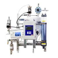
Figure 2: Purger Fill & Pre-Cool Cycle
Purge Cycle
e purge cycle consists of three main processes: ll & pre-cool,
separation of non condensable gases & refrigerant, and the safe
release of the non-condensable gases.
1. Fill & Pre-Cool (See Figure 2 for a graphic representation of
this cycle)
is cycle begins with high pressure liquid ammonia feeding
through the liquid solenoid, check valve and orice (causing
expansion) into the V300’s heat exchanger. e liquid
solenoid stays energized until the level of ammonia in the
heat exchanger is sensed by the level sensor. e level sensor
is strategically located so that all of the tubes in the heat
exchanger are lled with liquid ammonia. is guarantees
the highest level of performance.
e V300 Rapid Purger will stay in the “Pre-Cool” mode until
the shell of the heat exchanger reaches a temperature of 4.4ºC
(40ºF) or lower. is is determined by the temperature of the
suction the purger is tied into. Once the purger reaches the
required temperature, the purger will enter the active mode.
To prevent a vacuum type situation, the A2B evaporator
pressure regulator, located on the return suction line, is set at
Figure 3: Purger Separation of Non-Condensable Gases &
Refrigerant Cycle
0.34 barg (5 psig). is will prevent the heat exchanger from
reaching temperature below -29ºC (-20ºF).
2. Separation of Non-Condensable Gases & Refrigerant (See
Figure 3 for a graphic representation of this cycle)
Once the ll and pre-cool cycle reaches the desired
temperature and liquid level, it selects a purge point and
commences a purge cycle by activating a solenoid located on
the high side of the system, as illustrated in Figure 1.
With an active purge point, the non-condensable gases and
refrigerant mix, also known as foul gas, enters the shell side
of the heat exchanger through the liquid drainer, check valve
and a ow control orice. Any liquid that has condensed in
the purge lines will collect in the liquid drainer and return
directly to the suction. If the foul gas line does not contain
condensed liquid and any remaining liquid in the liquid
drainer evaporates to the suction, the liquid drainer ow
control ball will prevent any foul gas from entering the
suction line by blocking the orice at the bottom of the liquid
drainer tank, forcing the foul gas through the ow control
orice.
*Graphics for illustration only.
* *