37
GB IE
grinding discs may be used.
In general, work with small scrubs. Exert
only moderate pressure on the workpiece.
Always work in the counter-direction. This
ensures that the device is not pushed out of
the cut through lack of control.
Chuck key storage
The chuck key (13) can be stowed in the
handle (1).
1. Slot the chuck key (13) into the attach-
ment (25) on the handle (1).
2. Push the attachment (25) onto the hand-
le (1).
Ensure that the little marking on the attach-
ment (25) sits over one of the two re-
cesses at the upper end of the handle
(1), otherwise the handle (1) and the
attachment (25) will not slot into one
another.
Assembly
Caution! Risk of injury!
space in which to work, and that
you do not endanger other peo-
ple.
- All hoods and protective devices
must be assembled properly be-
fore commissioning.
- Disconnect the mains plug be-
fore changing the setting on the
device
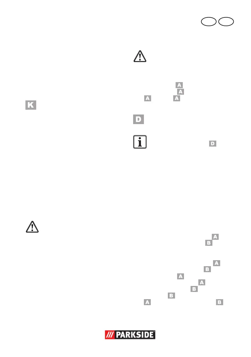
Mount handgrip
The device must only be
operated with the handgrip
mounted.
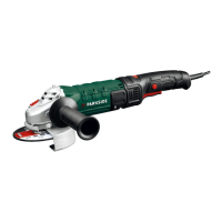
Depending on the method of working, tigh-
ten the handgrip ( 1) on to the handgrip
thread on the left ( 7), right (see illustra-
tion ) or top ( 2) of the device.
Assemble/set protective
hood/demounting
If the guard cover (9) is engaged in
the position illustrated in ,
push the whole guard cover against
the tool and turn it at the same time
Adjust the protective hood such that any
sparks or detached parts cannot hit either
the user or any bystanders.
The protective hood must also be positi-
oned such that the sparks cannot ignite
combustible parts, including those in the
surroundings.
Demounting the grinding disc:
1. Press the spindle stop button ( 10).
2. Turn the mounting spindle ( 16) until
spindle. Keep and continue to hold
down the spindle lock button ( 10)
3. Release the clamping nut ( 15) with
the chuck key ( 13). You can release
the spindle lock button ( 10).
4. Take off the locknut ( 15), the adap-
14) and cutting disc
( 16).