7
76 cm
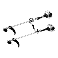
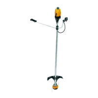
CONFIGURING YOUR UNIT
You can configure your unit usinga cuttinghead
for grass and light weeds, or a weed blade for
cutting grass, weeds, and brush up to 1 cm in
diameter. To assemble your unit, go to the sec-
tion for the desired configuration and follow the
instructions.
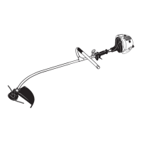
ASSEMBLY INFORMATION --
TRIMMER HEAD
TRIMMER
HEAD
NOTE:Remove theblade andmetalshieldbe-
fore attaching the plastic shield and trimmer
h ead. To re mo ve blade, align hole in the dust
cup with theholein theside ofthe gearbox by
rotating the blade. Insert a smallscrewdriver
intoalignedholes. Thiswillkeepthesha ftf rom
turning while loosening the blade nut. Remove
blade nut by turning clockwise. Remove the
screwdriver. Remove both washers and blade.
To remove metal shield, loosen and removethe
four mounting screws. See A TT ACHING THE
MET AL SHIELD and INST ALLA TION OF THE
MET ALBLADEforillustrations. Besuretostore
all parts and instructions for future use.
ATTACH ING THE PLASTIC SHIELD
ANDTRIMMERHEAD
WARNING: Theshieldmust beprop-
erly installed. The shield provides partial
protectionto the operatorandothers fromthe
risk of thrown objects, and is equipped witha
line limiterbladewhichcuts excess line tothe
proper length. The line limiter blade (on un-
derside of shield) is sharp and can cut you.
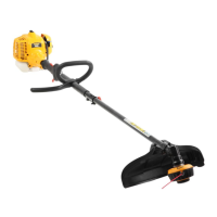
1. Remove nut from shield.
2. Insert bracket into slot on shield.
3. Pivot shielduntil boltpasses throughhole
in bracket.
4. Reinstall nut and tighten securely with
wrench (provided).
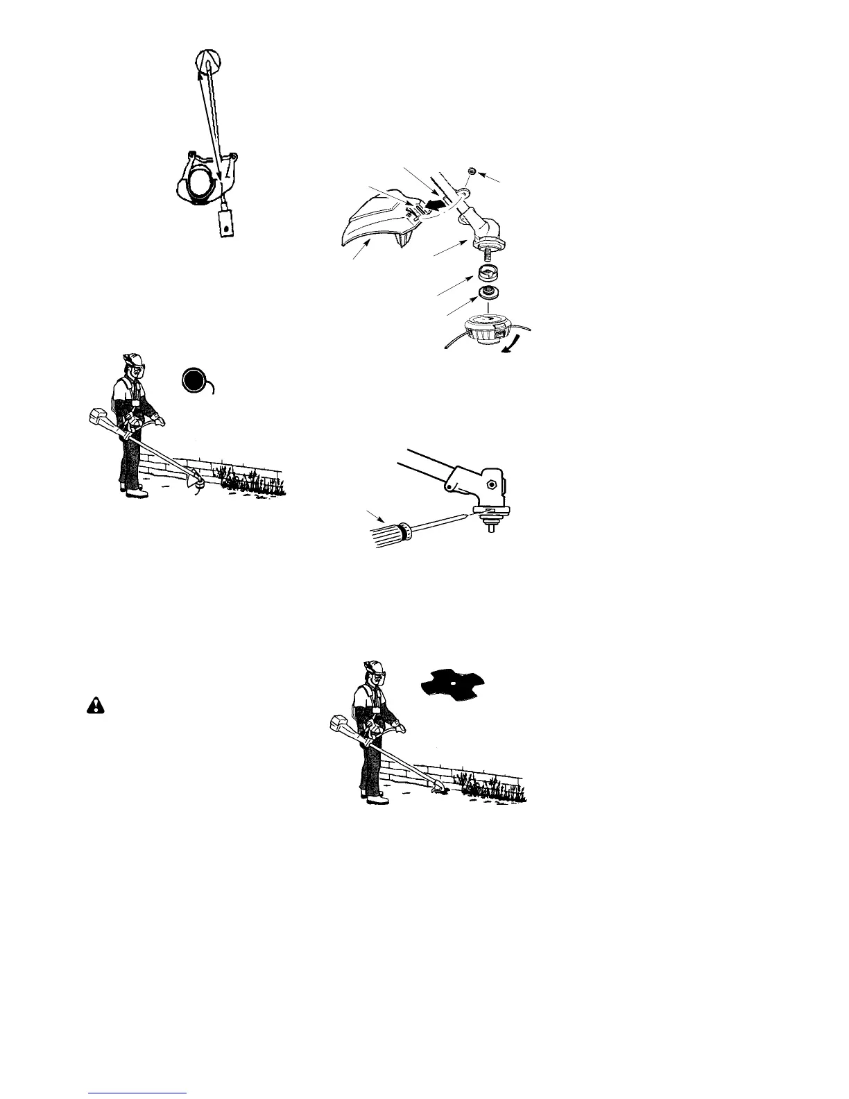
NOTE: If your unit has a plastic cover over
thethreadsonthethreadedshaft,removethe
coveringtoexposethethreads.Beforeinstal-
lingthetrimmerhead,makesurethedustcup
and retaining washer are positioned on the
gearbox as shown below .
Nut
Retaining Washer
Dust C up
Bracket
Slot
Shield
Gearbox
NOTE: Make sure all parts are properly
installed as shown in the illustration before
installing the trimmer head.
5. Align hole in the dust cupwith thehole in the
sideof the gearbox by rotating the dustcup.
6. Insert a small screwdriver into aligned
holes. This willkeeptheshaftfromturning
while tightening trimmer head.
Screwdriver
7. While holding the screwdriver in position,
thread trimmer head onto the shaft in the
direction shown on the decal (counter-
clockwise). Tighten until secure.
NOTE: The retaining washer must be posi-
tioned with the raised section facing toward the
gearbox.
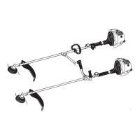
ASSEMBLY INFORMAT ION -- WEED
BLADE
WEED
BLADE