DS 350 G Boom Control Troubleshooting- TMS/TTS870 / RT865 BXL
031-300-190-039 Rev. B 4/30/99
13
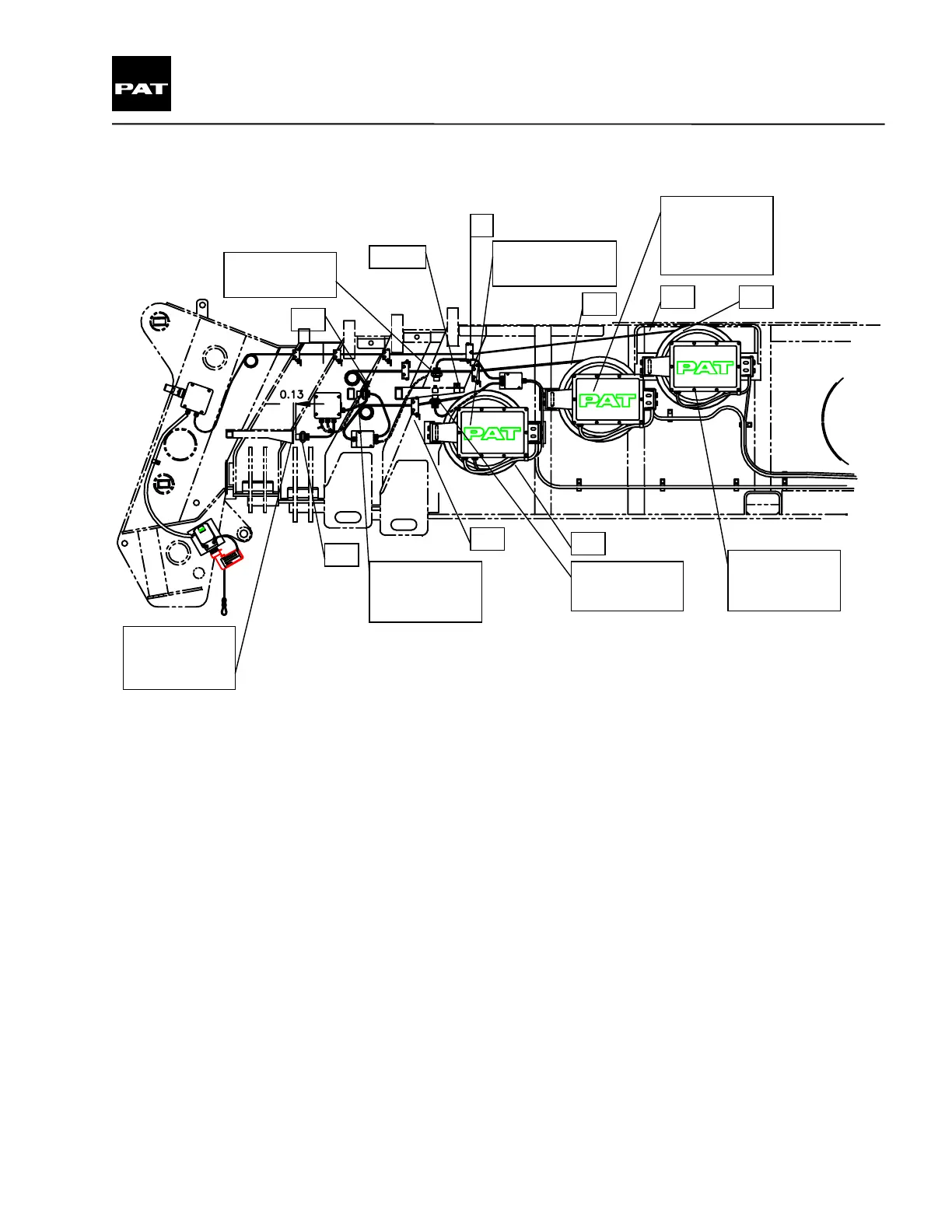
9.1 DS 350 G - Boom Components and Setup
Outer mid
retract and %
reset switch
Center mid
retract and %
reset switch
Inner mid
retract switch
Inner mid %
reset switch
Inner mid length
sensor LG 221
Center mid
length and
angle sensor
LWG 221
Overall boom
length sensor
LG 208
1
3
2
4
4
5
7
7
8 / 9
Drawing 4.
1. Pre-tension the cable reel spring by rotating drum (16) revolution counterclockwise. If replacing the LG 208
un-spool the length cable and secure to bushing on the boom nose as noted in the installation drawing. Zero
the length potentiometer as described on page 18.
2. Pre-tension the cable reel spring by rotating drum (35) revolution counterclockwise. If replacing the LG 221
un-spool the length cable and secure to bushing on the boom nose as noted in the installation drawing. Zero
the length potentiometer as described on page 18.
3. Pre-tension the cable reel spring by rotating drum (30) revolution counterclockwise. If replacing the LWG 221
un-spool the length cable and secure to bushing on the boom nose as noted in the installation drawing. Zero
the length potentiometer as described on page 18.
4. Run cable through the cable guides. Remove 1/4-20 nuts on bottom of cable guide, insert cable guide
screws through existing angle bracket and secure in place with 1/4-20 nuts removed previously.
5. Center line of cable must be aligned with center line of cable drum. See partial top view.
PAT Equipment Corporation reserves proprietary rights to this drawing and to the data shown there on. The drawing and data are
confidential and are not to be used or reproduced without the written consent of PAT Equipment Corporation. This drawing is subject to
technical modification without prior notice.
 Loading...