17
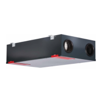
Fig. 15: Fixing the two base parts
3. Now connect the other two base parts in the same way.
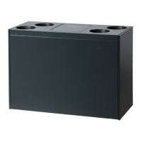
Fig. 16: Two sets of base parts fixed together
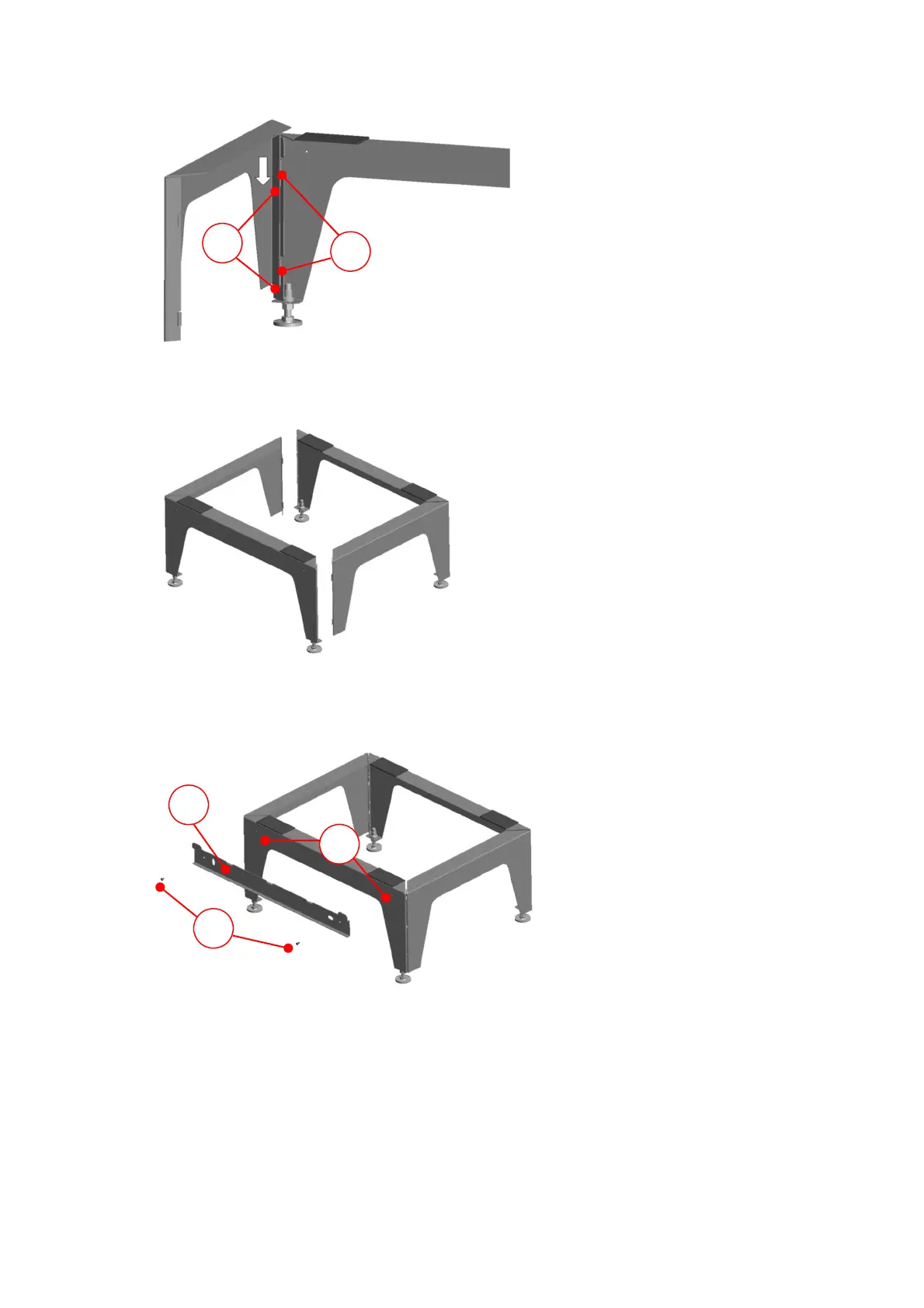
4. Mount the fastening sheet C on the long base part with the lugs pointing upwards. To do this, screw the two
Parker screws D into the holes provided E on the base part so that they go through the fastening sheet.
Fig. 17: Mounting the fastening sheet on the base part
5. Now use the height-adjustable feet F to adjust the fully assembled floor stand on the designated set-up area so
that it is plumb vertical and stable. Then fix it in this height position with the lock nuts of the adjustable feet.
A
B
C
E
D
 Loading...