21
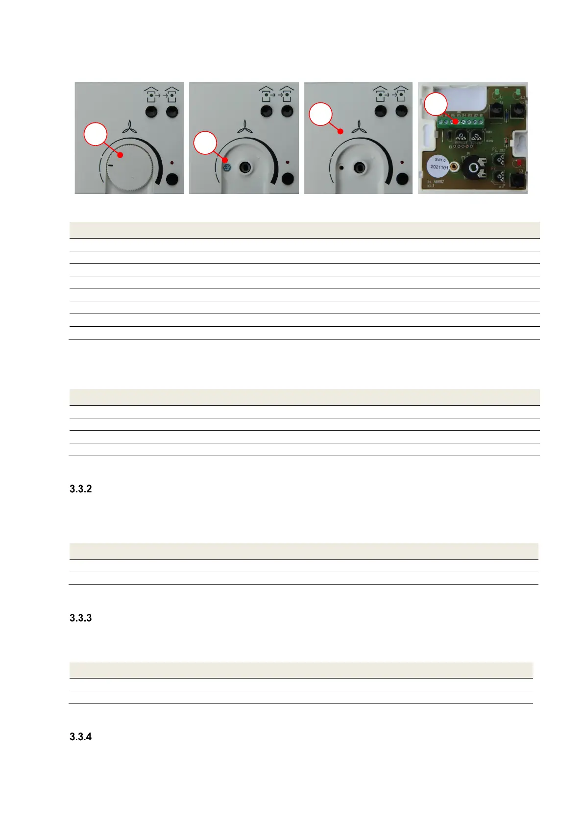
To open the control panel, proceed as follows:
1. Remove rotary knob
2. Fully unscrew and
remove fixing screw
3. Remove top section of
control panel
4. Access control panel
connecting terminal
Control panel connecting terminal Signal
X.01 +12 V
X.02 U
s
(supply fan control voltage)
X.03 U
s
(extract air fan control voltage)
X.04 GND
X.05 Analogue input 0–10 V
X.06 Analogue input GND
X.07 Input for external boost ventilation button
X.08 GND input for external boost ventilation button
Tab. 5: Control panel connecting terminal assignment
3.3.1.2 Connecting the connecting cable to the control board
Connect the connecting cable to the X0 4-pin screw-type terminal on the control board in accordance with Tab. 6.
X0 terminal on control board Signal
X0.01 +12 V
X0.02 U
s
(supply fan control voltage)
X0.03 U
s
(extract air fan control voltage)
X0.04 GND
Tab. 6: X0 terminal assignment on control board
Connecting external boost ventilation buttons
Boost ventilation mode can be activated by operating one or more boost ventilation buttons (connected in parallel). The
buttons that are usually installed as part of the switch range design are triggered when boost ventilation mode is
selected. To establish the potential-free connection between the button and control panel connecting terminal, use a
2-core cable as a minimum (recommended cable type: J-Y(ST)Y 2x2x0,6).
Control panel connecting terminal Wire of boost ventilation button cable
X.07 Wire 1
X.08 Wire 2 (GND)
Tab. 7: Terminal assignment of boost ventilation button connection
Connecting external sensors
A sensor-controlled automatic mode is supported. This is controlled by an analogue 0–10 V sensor signal generated
by one or more sensors. To establish the connection between the sensor module and control panel connecting terminal,
use the type of cable stipulated for transmitting the sensor signal.
Control panel connecting terminal Wire of sensor module cable
X.05 Wire 1 (0–10 V sensor signal)
X.06 Wire 2 (GND)
Tab. 8: Terminal assignment of analogue sensor signal connection
Connecting an external pre-heater
If there is an optional electric pre-heater, this must be connected to terminals X2/X4b of the control board. Feed the
pre-heater power cable through a cable guide and fix it in place using a cable gland for strain relief.
1.
2.
3.
4.
 Loading...