38
COMBUSTION-
AIR
COMBUSTION-
AIR
AIR
FLOW
VENT
VENT
VENT
AIR
FLOW
AIR
FLOW
AIR
FLOW
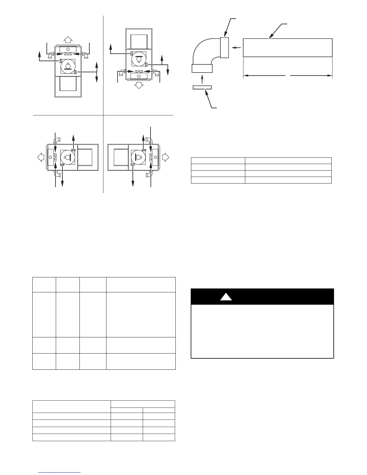
UPFLOW DOWNFLOW
HORIZONTAL-LEFT DISCHARGE HORIZONTAL-RIGHT DISCHARGE
Select 1 vent pipe connection and
1 combustion-air pipe connection.
COMBUSTION-
AIR
COMBUSTION-
AIR
COMBUSTION-
AIR
COMBUSTION-
AIR
VENT
VENT
VENT
NOTE: Select 1 vent pipe connection and
1 combustion-air pipe connection.
NOTE:
* For Non-Direct Vent (1-Pipe) system, orient elbow so that its
opening faces down.
** For Non-Direct Vent (1-Pipe) system, orient elbow so that its
opening faces sideways.
† An external trap kit (see furnace product data sheet) must be used.
*
*
**
**
†
†
†
†
††††
† †
Bottom combustion-air not allowed for non-direct vent
A05092
Fig. 38 -- Combustion-Air and Vent Pipe Connections
Tab le 11 – Furnace Setup Switch Description
SETUP
SWITCH
NO.
SWITCH
NAME
NORMAL
POSITION
DESCRIPTION OF USE
S W --- 1
Adaptiv
eHeat
Mode
OFF
When off, allows 2---stage
operation with a
single---stage thermostat.
Tu r n o n w h e n u s i n g 2 --- s t a g e
thermostat to allow Low
Heat operation when R to
W/W1 closes and High Heat
operationwhenRtoW/W1
and W2 close.
S W --- 2
Blower
OFF
delay
ON or
OFF
Control blower OFF delay
time. Used in conjunction
with SW---3. See Table 9B.
S W --- 3
Blower
OFF
delay
ON or
OFF
Control blower OFF delay
time. Used in conjunction
with SW---2. See Table 9B.
Tab le 12 – Blower Off D elay Setup Switch (SW)
2-Stage Units
DESIRED HEATING MODE
BLOWER-OFF DELAY (SEC)
SETUP SWITCH
S W --- 2 S W --- 3
90 OFF OFF
120 OFF ON
150 ON OFF
180 ON ON
FIELD-SUPPLIED
2-IN. (51 mm) DIA.
PVC PIPE
FIELD-SUPPLIED
2-IN. (51 mm) DIA.
PVC 90° ELBOW
COMBUSTION-AIR DISC
(FACTORY-SUPPLIED IN
LOOSE PARTS BAG)
A
A96211
Fig. 39 -- Combustion--Air Inlet Pipe Assembly
Length of Straight Pipe Portion of
Combustion-Air Inlet Pipe Assembly --- (IN / mm)
CASING WI DTH A
17---1/2 (445) 8 --- 1 / 2 ±1/2 (216 ±13)
21 (533) 10---1/2 ±1/2 (267 ±13)
24---1/2 (622) 12 ±1/2 (305 ±13)
NOTE: (Direct Vent/2-pipe ONLY) vent pipe system has the
same diameter and same length as combustion air pipe mentioned
in section “Assembly of Combustion Air Pipe (Direct Vent/2-Pipe
system ONLY).”
NOTE: Do not count elbows or pipe sections in terminations or
within furnace (all elbows shown in Fig. 4 4 and Fig. 45 are not be
to counted).
2. Determine location of vent pipe connection to inducer
housing as shown in Fig. 38 for application.
3. Install vent pipe grommet (factory-supplied in loose parts
bag) into selected furnace casing vent pipe hole. (See
Fig. 40.)
4. Reposition elastomeric (rubber) inducer housing outlet cap
and clamp to appropriate unused inducer housing
connection. Tighten clamp.
CARBON MONOXIDE POISONING AND PROPER TY
DAMAGE HAZARD
Failure to follow this warning could result in property damage,
personal injury or death.
Inducer housing outlet cap must be installed and fully seated
against inducer housing. Clamp must be tightened to prevent
any condensate leakage.
!
WARNING
5. Be certain that mating surfaces of inducer housing
connection elastomeric (rubber) coupling, and 2-in. (51
mm) diameter vent pipe are clean and dry. Assemble the
elastomeric (rubber) vent coupling (with 2 loose clamps)
onto inducer housing connection. Insert the 2-in. (51 mm)
diameter vent pipe through the elastomeric (rubber)
coupling and fully into inducer housing connection until it
touches a stop inside the inducer housing outlet. Tighten
the screws o n both clamps to 15-in-lb. of torque. pipe to
inducer housing. Tighten the clamp screws to 15 in.-lb. o f
torque.
NOTE: Starting at furnace, slope vent pipe a minimum of 1 /4-in.
(6 mm) per linear ft with no sags between hangers.


 To Next Page