5
A. SETTING THE BOILER
1. Provide a level foundation, located as close as
possible to the center of the heating system.
2. Refer to Figure 2.3 for exploded view of boiler while
checking and/or assembling parts of the boiler.
3. See clearance information in Section 1,
“Preinstallation.”
4. On packaged boilers, open burner mounting plate
(Item 4) at this time to make certain the target wall
(Item 2) is seated in the back of the combustion
chamber. Ceramic fiber blanket base liner (Item 3)
should be lying flat on bottom of combustion
chamber between target wall and burner.
B. FLUE BAFFLES - EC(T)-e MODELS ONLY
1. Flue baffles are for use on EC(T)-e models only.
Do not install flue baffles on EC-05-250 or EC-06
models. Applicability of flue baffles is also shown in
burner specification tables in Section 5.
2. Packaged Boilers - Flue baffles are factory installed
in 03 thru 05 section boilers. Remove flue baffles if
converting to EC-05-250 rate.
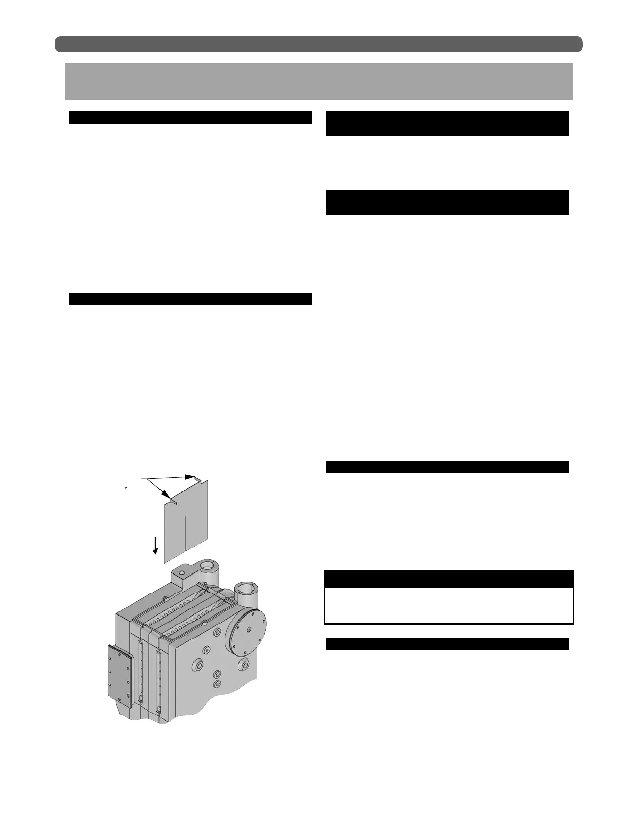
3. Knock-Down Boilers - Flue baffles are located in
03 thru 05 section jacket cartons. Bend baffle tabs as
shown in Figure 2.1 and suspend baffles from top of
flueways. Install one baffle per flueway. Do not install
baffles if converting to EC-05-250 rate.
C. OBSERVATION COVER ASSEMBLY
(KNOCKDOWN BOILERS)
1. Remove observation door (Item 6) from inside
burner mounting plate. Attach the observation door
to the outside of the mounting plate.
D. INSTALLATION OF FLUE COLLECTOR &
COVERPLATES (KNOCKDOWN BOILERS)
1. Open flue collector carton. Remove flue collector
(Item 13) and high temperature rope. Lay rope
(Item 14) on top of boiler against bead provided.
Place flue collector on top of rope and attach to
boiler with 1/4”-20 x 1-3/4” studs with nuts through
flue collector brackets into the tapped lugs provided
in the top of the boiler end sections. Draw nuts down
snugly.
2. Remove clean-out cover plates and insulation
(Items 24 and 25). Each clean-out cover plate is
attached to the boiler by using two carriage bolts,
nuts and washers (Item 26). Install the carriage bolts
into the notch at the top and bottom of each clean-
out opening, then secure them with a flat washer
and steel nut as shown in Figure 2.2 locking them
in place. Press the clean-out plate with insulation
over the protruding carriage bolts until the bolts
punch through the insulation so flat washer and
brass nut can be installed. Tighten down nuts snugly
compressing the insulation to form a good seal
around the clean-out opening.
E. TANKLESS HEATER OR COVERPLATE
If an ECT steam boiler is to be installed with a tankless
heater coil, the coil must be installed before the left side
jacket panels are attached. When a tankless heater is
not employed, cover the heater opening with cover plate
(Item 17 or 21).
See Section 3, Piping and Controls, for piping
information.
F. JACKET ASSEMBLY
1. Refer to Figure 2.3 for exploded view.
2. Attach the back panel to bosses on middle of back
section with two 1/4” x 3/8” truss head machine
screws (Item 27) provided. The back panel has two
5/16” diameter holes close to the center of the panel.
3. Lift off the burner mounting plate.
2. BOILER PLACEMENT & ASSEMBLY
BOILER PLACEMENT & ASSEMBLY
Be sure rubber gasket is in place between cover
plate or water heater plate and boiler section.
NOTICE
INSTALL FLUE
BAFFLES ON
EC(T)-e MODELS,
1 PER
FLUEWAY.
BEND TABS
90
IN
OPPOSITE
DIRECTIONS
Figure 2.1: Flue Baffle Installation, EC(T)-e Models