6
BOILER PLACEMENT & ASSEMBLY
4. Insert ceramic fiber blanket base liner (Item 3) on
bottom of combustion chamber between target wall
and burner. Verify that the target wall is seated in the
back of the chamber.
5. Remove the (2) knock-outs in the front jacket panel
which allow clearance for the hinge. Place the front
jacket panel on the block and replace the burner
mounting plate.
6. Attach right side jacket panel to the front and back
panels with sheet metal screws (item 28).
7. On steam boilers, if a tankless heater is used, remove
the knock out in upper left side jacket panel and
back jacket panel before installing. Attach left side
jacket panels in the same manner as the right side
panel.
8. Attach the top panel. Secure top panel to front and
back panel with sheet metal screws.
9. Attach rating label and clearance/burner specification
label to jacket. Labels are located in boiler folder
which is located in jacket carton.
G. FLUE COLLAR
Secure the flue collar to the vent connector and join
the sections of the vent connector using sheet metal
screws or per listed vent manufacturer’s instructions.
WARNING
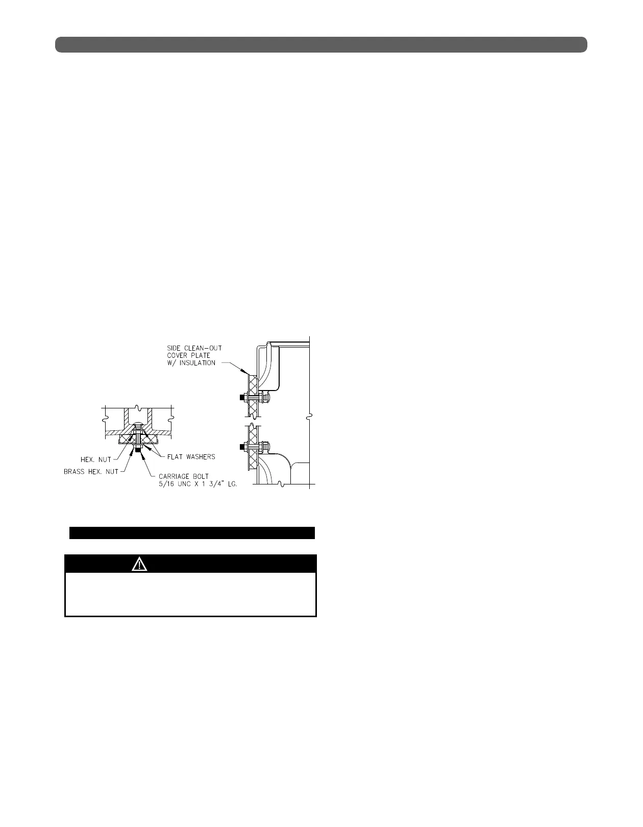
Figure 2.2: Side Clean-out Cover Plates