66
L510010-07A
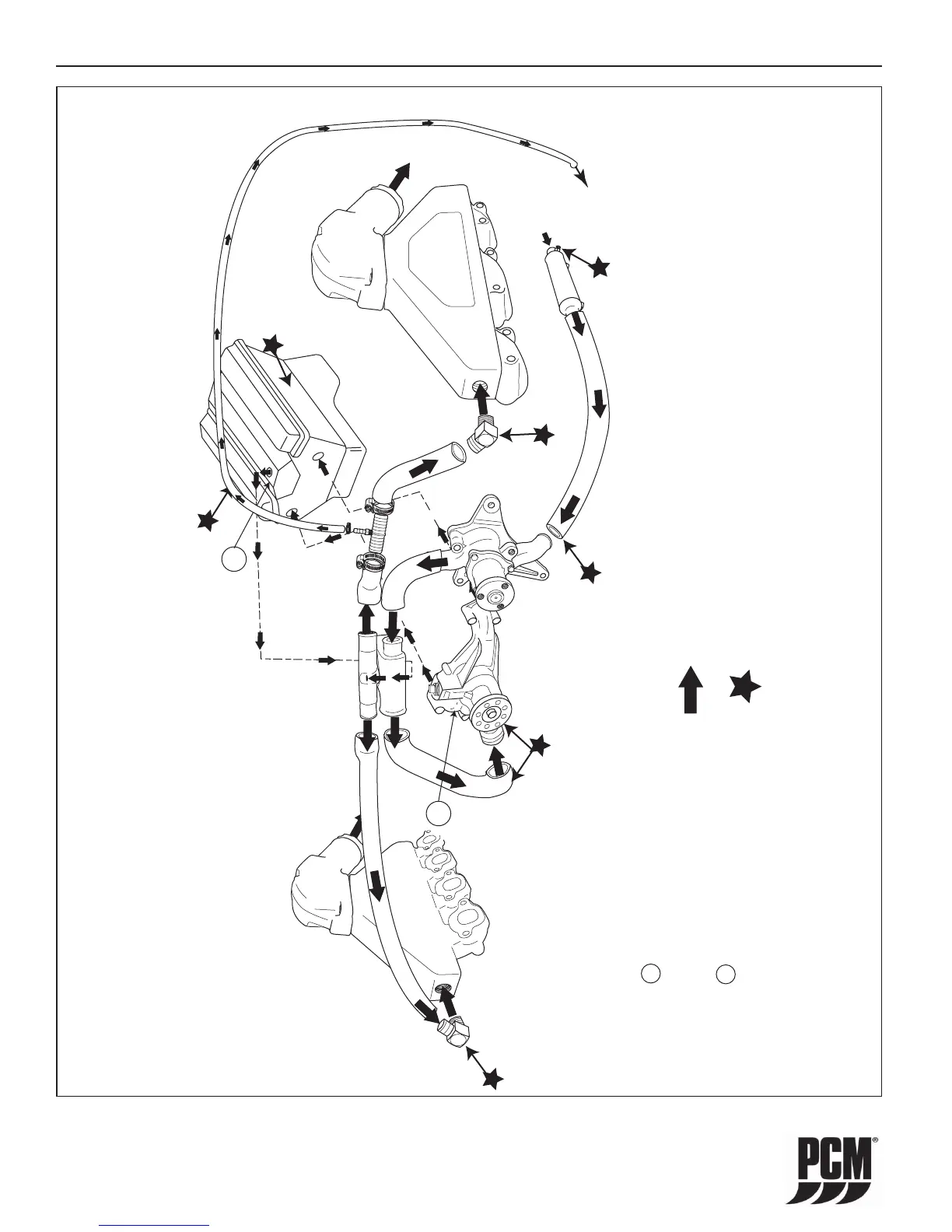
WATER FLOW DIAGRAMS - 15
= RAW WATER FLOW
= Drain Locations
Knock Sensor
Torque 20 N
.
m (15 lb ft)
IMPORTANT: Accessory (i.e.
heater, hot water tank) Hook Up
Location 1 - Water OUT to
heater or hot water tank. T-Fitting
required at temp. sender location.
Location 2 - Water RETURN
from heater or hot water tank.
Fitting at circulating pump.
2
1
TO DRIPLESS
SHAFT SEAL
IMPORTANT: The water supply hose to the
Dripless Shaft Seal must be routed to prevent
siphoning of the engine cooling water.
Typically, the suppy hose is routed upward
above the engine block then down to the
shaft seal.
Figure 15-1 Raw-Water Cooling System (5.0/5.7L Modular Raw Water Pump)
 Loading...