48
L510010-11
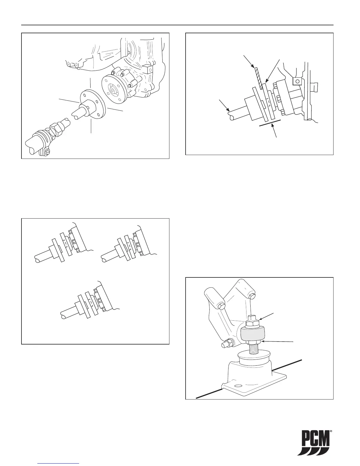
3. Check that the coupling center lines align by
butting the propeller shaft coupling against
the transmission coupling (Figure 11-26). The
shoulder on the propeller shaft coupling face
should engage the recess on the transmission
coupling face, with no resistance.
Figure 11-25 Centering Prop Shaft
B
B
A
A
IMPORTANT: Offset misalignment conditions must be
corrected prior to checking for angular misalignment.
NOTICE: Some propeller shaft couplings may not have
a shoulder on the mating surface. On these installations,
use a straight edge to check the centerline alignment
(Figure 11-27).
Figure 11-26 Shaft Mating Surface Check
OFFSET
MISALIGNMENT
ANGULAR
MISALIGNMENT
PERFECT ALIGNMENT
COUPLING FACES ARE PARALLEL
WITH DISTANCE BETWEEN FACES
EXACTLY THE SAME AT ALL POINTS
Figure 11-27 Angular Alignment
STRAIGHT
EDGE
TRANSMISSION
OUTPUT FLANGE
.003 INCH
(0.07 mm)
FEELER GAUGE
PROPELLER
SHAFT
COUPLING
FLANGE
OFFSET ALIGNMENT:
4. If the coupler center lines are not aligned, adjust
the mounts as follows:
• UP or DOWN OFFSET ADJUSTMENT:
Loosen the locking nut. Turn the adjusting
nut or the adjusting bolt in the direction
required to raise or lower the engine. After
the adjustment is complete, tighten the
locking nut.
IMPORTANT: For Offset Alignment, both front mounts
(or rear mounts) must be turned equally or angular
misalignment will occur.
Figure 11-28 Mount Adjustment
LOCKING
NUT
ADJUSTING
NUT
ENGINE MAINTENANCE - 11
 Loading...