49
L510010-11
ENGINE MAINTENANCE - 11
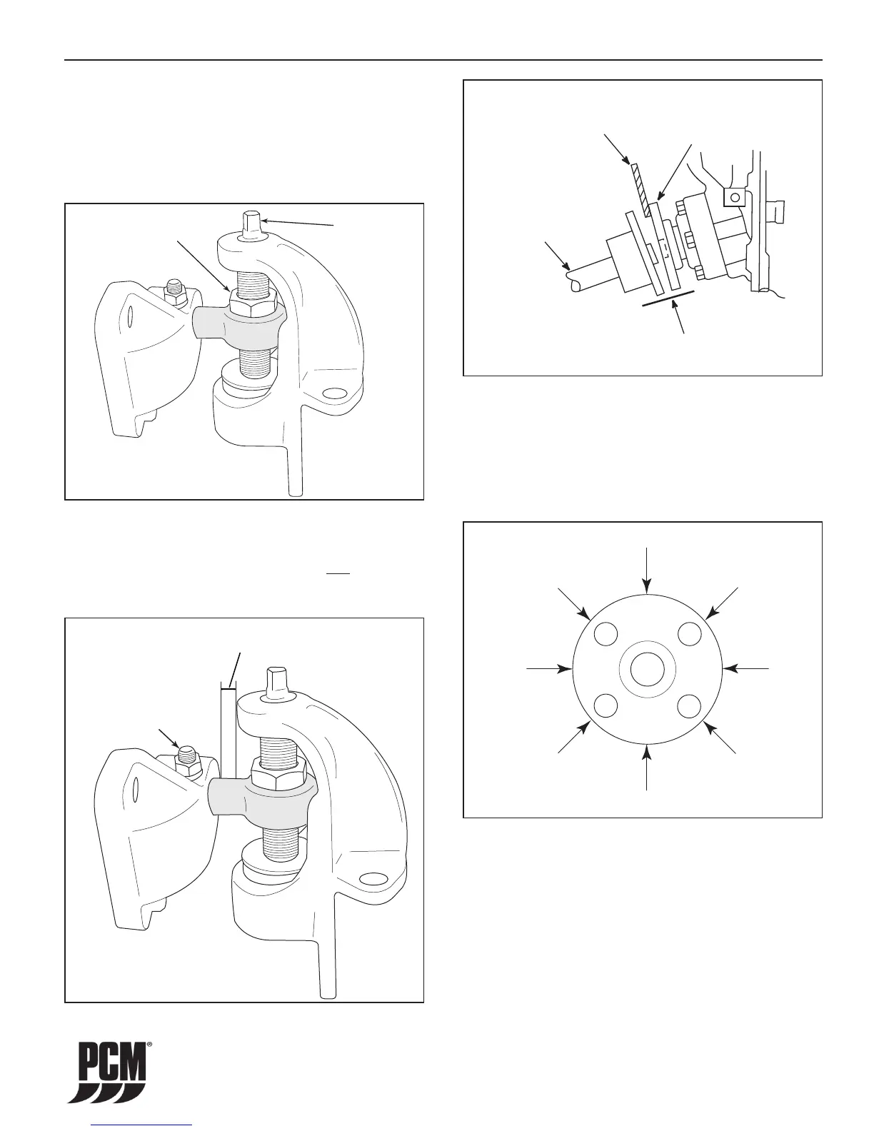
Figure 11-30 Engine Extension
TRUNNION
BOLT
1.750 in. MAX
(44.45 mm)
Figure 11-29 Mount Adjustment
LOCKING
NUT
ADJUSTING
BOLT
• LEFT or RIGHT ADJUSTMENT: Loosen
the trunnion clamping bolt and the nut on all
four mounting brackets. Move the engine
to the left or right, as necessary, to obtain
the proper alignment. After adjustment is
complete, tighten all bolts.
IMPORTANT: The large diameter of the mount trunnion
MUST NOT extend over 1.750 in. (44.45 mm), from the
mounting brackets on any of the mounts; and a suffi cient
amount of the trunnion must remain in the mount to be
secured by the trunnion locking bolt.
Figure 11-31 Angular Alignment
STRAIGHT
EDGE
TRANSMISSION
OUTPUT FLANGE
.003 INCH
(0.07 mm)
FEELER GAUGE
PROPELLER
SHAFT
COUPLING
FLANGE
5. Check for any angular misalignment. Hold
coupling faces tightly together by hand and check
for a gap between the coupling faces, with a
0.003 in. (0.07 mm) feeler gauge, at 90-degree
intervals. (Figure 11-31).
Figure 11-32 Angular Alignment Check
A
A
B
B
RC
RC
LC
LC
IMPORTANT: Angular misalignment conditions may
require adjustment of one front mount, both front
mounts, the trunnions, or any combination. Figure 11-32
(Angular Alignment Check) and the following table are to
assist in the alignment process.
 Loading...