75
L510010-11
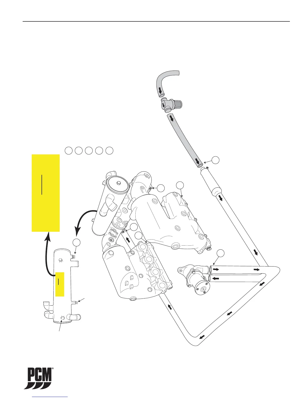
WATER FLOW DIAGRAMS - 15
Figure 15-11 Direct Drive Half-System ZR450 CES
Note: This diagram is for illustration purposes
only. The actual routing and/or shape of the
hoses may vary slightly depending on installation.
Heat Exchanger - Rear View
1
1
2
2
3
3
4
4
4
5
5
5
Drain Locations
- Transmission Cooler - Remove Inlet Hose
- Raw Water Pump - Remove Outlet Hose
- Heat Exchanger - Remove Drain Plug/Zinc Anode
- Exhaust Manifolds - Remove Hose
- Exhaust Corners - Remove Drain Plugs
Raw Water
Drain/Zinc
Anode
Fresh Water
Drain
Shaft Seal
Fitting
WARNING
WARNING
THE ENGINEEXHAUST SYSTEM MUST BECOMPLETELY DRAINEDFOR WINTERIZATION.
REFER TOTHE SPECIAL INSTRUCTIONS PROVIDED
FOR THEPROPER DRAINING PROCEDURE.
WARNING
WARNING
THE ENGINE EXHAUST SYSTEM MUST BE COMPLETELY DRAINED FOR WINTERIZATION.
REFER TO THE SPECIAL INSTRUCTIONS PROVIDED
FOR THE PROPER DRAINING PROCEDURE.
 Loading...