Brought to you by PCS Electronics, www.pcs-electronics.com
Front and back panel layout
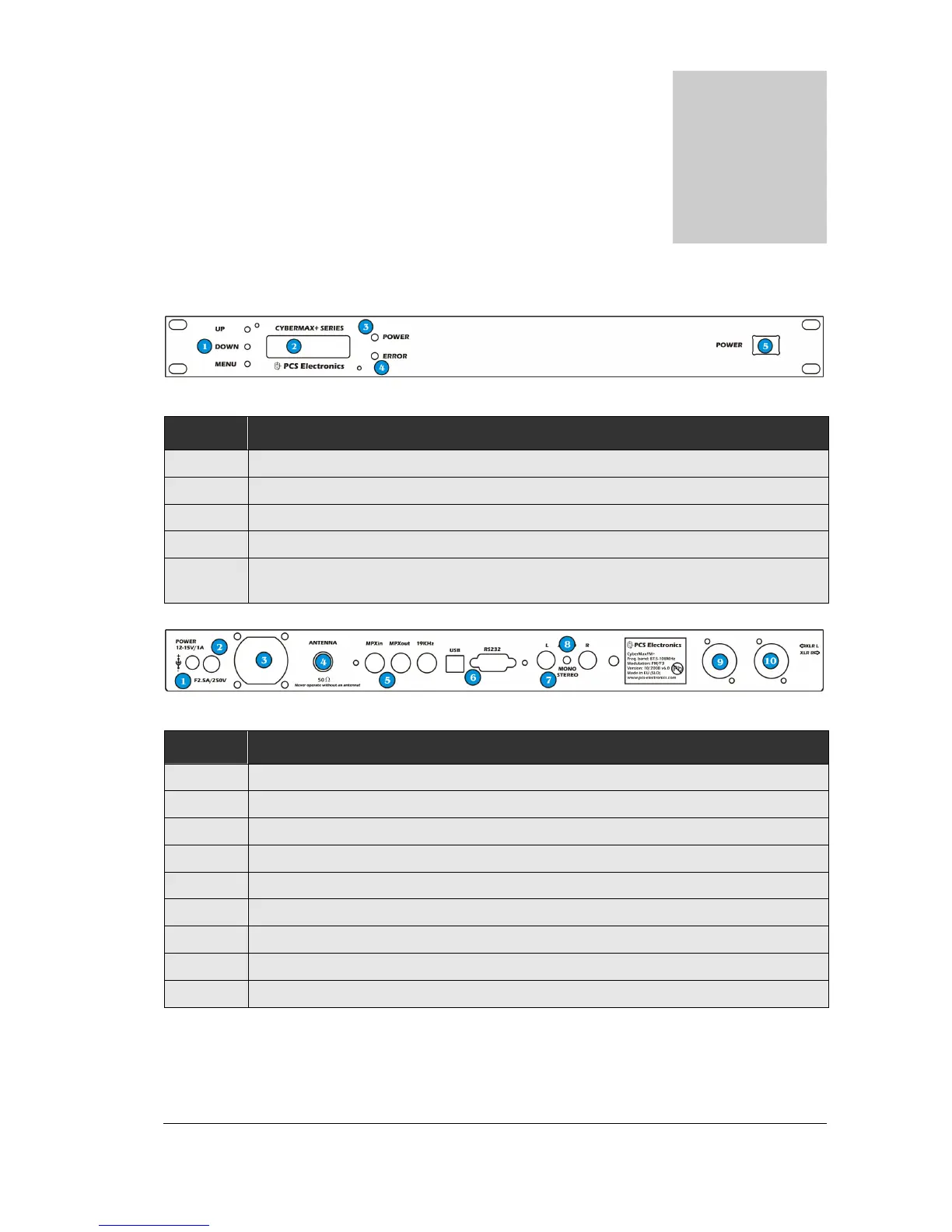
Fig. 1: Front panel
Reference Function
1 Three push buttons, the UP, DOWN and MENU keys.
2 LCD display that lets you control the unit and monitor various parameters.
3 The green led. Green signals power is ON.
4 Red error led. Turns on while VCO is tuning into selected frequency and in case of SWR or TEMP error.
5 Power switch in the middle of the panel is actually a standby switch. To really disconnect the unit from
mains power use the main switch at the back.
Fig. 2: Back panel
Reference Function
1 Power jack, center is positive. 12-15V DC, 2.5A
2 Fuse, F3A/250V
3 Ventilation aperture
4 Antenna connector, BNC. Do not operate without antenna.
5 BNC connectors for MPXin, MPXout and 19KHz pilot.
6 RS232/USB for controlling your RDS encoder.
7 Audio inputs, RCA jacks for left and right channel
8 STEREO mode indicator.
9, 10 Balanced audio inputs, left and right channel XLR (Canon)