Brought to you by PCS Electronics, www.pcs-electronics.com
What’s inside the box?
CyberMaxFM+ 15W units are available in several configurations. Exact internal configuration depends on the particular
model. Since we sometimes change configurations it is best to check our website for latest information. Below are the basic
building blocks of the exciter. Note that the RDS encoder is optional and only available in models with RDS capability.
Similarly DSP encoder is only available in DSP capable models. We are now going to have a look at these building blocks
one at a time:
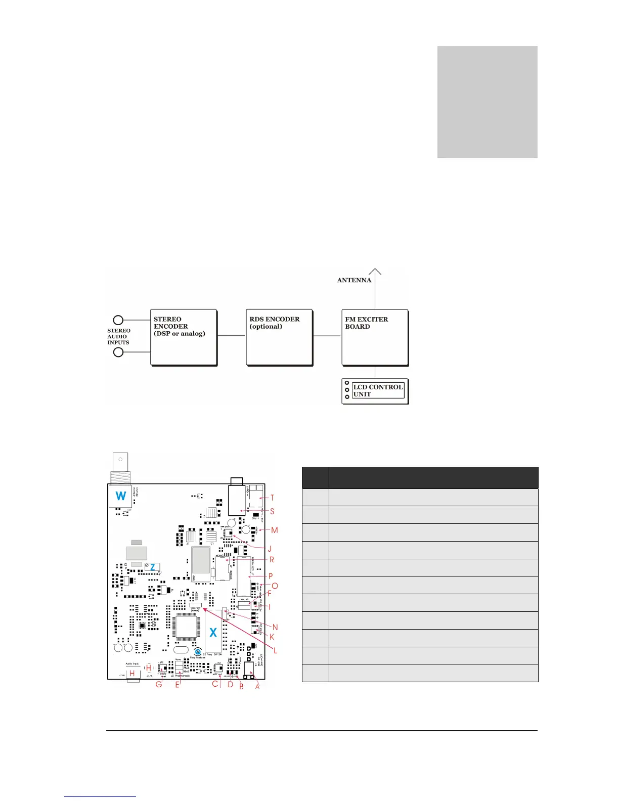
Fig. 3: Block diagram of the CyberMaxFM+ transmitter
FM Exciter board
15W CyberMaxFM+ units utilize our MAX PRO series FM exciters
Fig. 4: MAXPRO3000+ FM exciter board layout
Ref Function
A On-OFF switch
E Pre-emphasis. For mono operation set to OFF
G Modulation level
H Audio input
R 6-pin header to the stereo encoder
P 14-pin header to the LCD module
J LCD power meter accuracy
M FAN power pads
S Fuse, F3A250
T Power supply, (+) center, 12-15V/3A stabilized
W Antenna connector, BNC