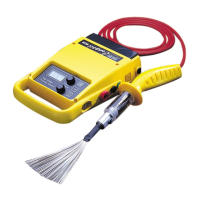
4.0 CONTROL PANEL LAYOUT
1 LCD display (including battery condition
indicator)
2 Voltage control (10 turn)
3 Visual alarm indicates when fault is found
4 On switch
5 Off/test switch
6 Sensitivity control for the alarm
7 Audible alarm when fault is found
8 High Voltage probe connector
9 Fuse (1.6A slow blow) 5 x 20mm
10 Earth connection point
11 Slide-off power pack
12 Earphone jack (opposite side)
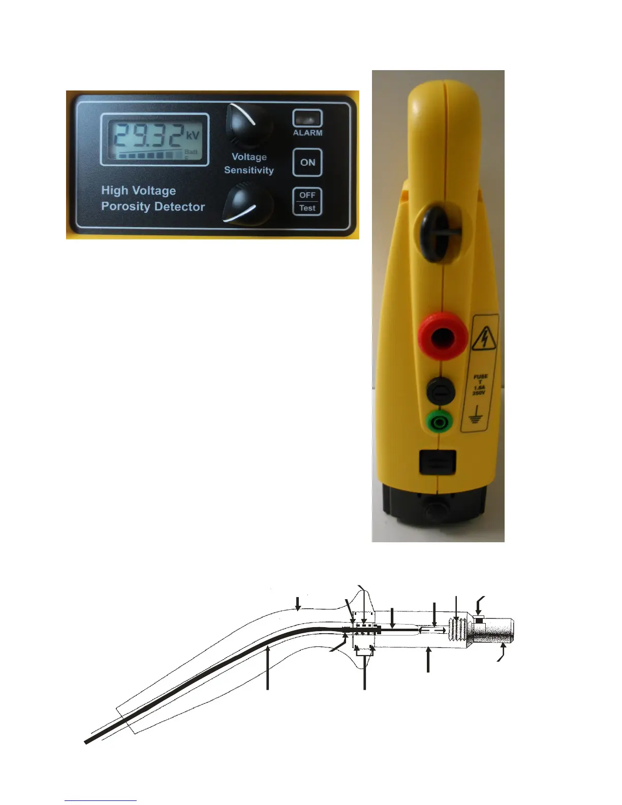
Carbon Cored Lead “O” Rings
Screw Fitting
Neon
Lock Nut
End Cap
Neon Holder
Screw
Probe Handle
Washer