Gettina Started
Meter Functions
-
Diode Check
U
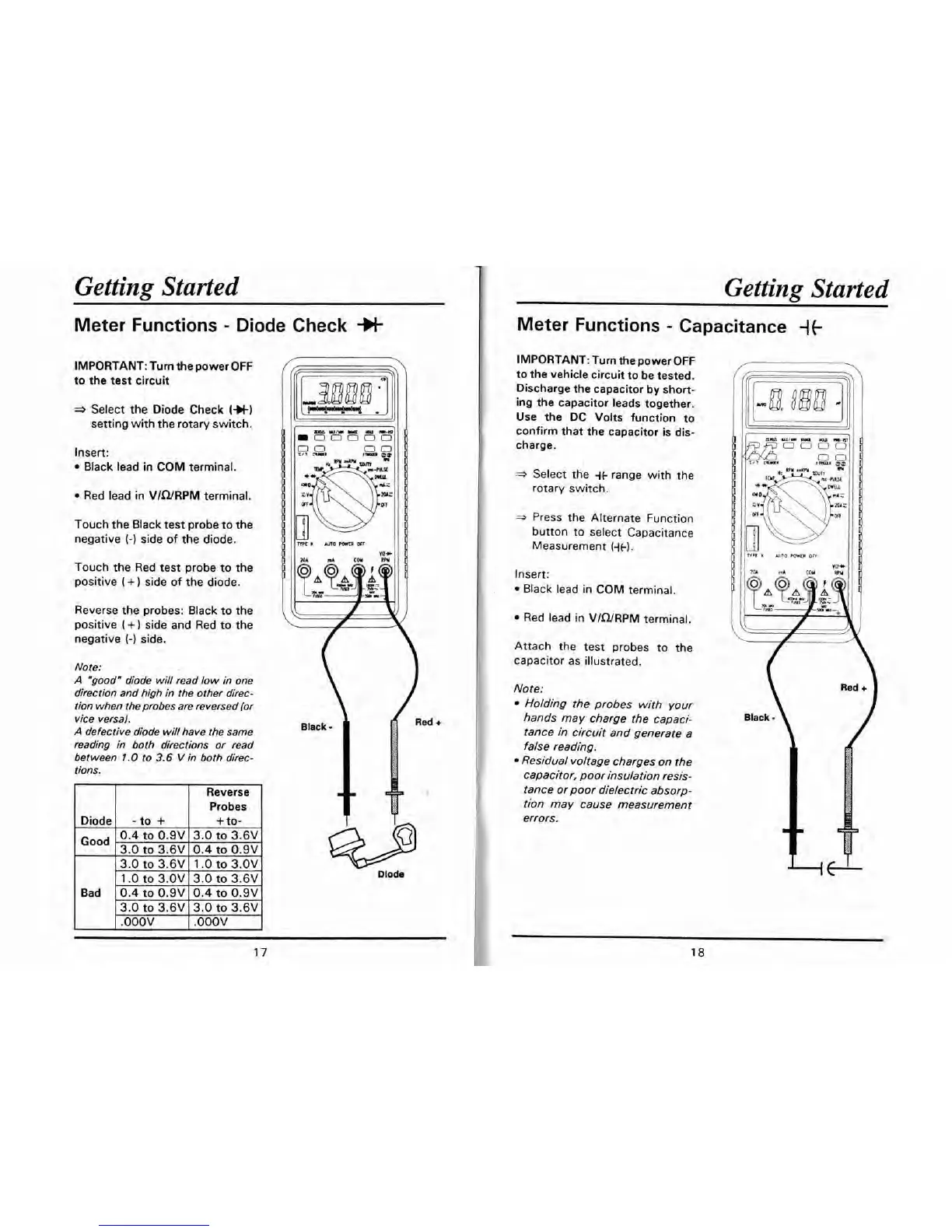
IMPORTANT: Turn the power OFF
to the test circuit
a
Select the Diode Check
(+t)
setting with the rotary switch.
Insert:
Black lead in COM terminal.
Red lead in VIWRPM terminal.
Touch the Black test probe to the
negative
(-1
side of the diode.
Touch the Red test probe to the
positive
(
+
)
side of the diode.
Reverse the probes: Black to the
positive
(+)
side and Red to the
negative
(-1
side.
Note:
A
"good" diode will read low in one
direction and high in the other direc-
tion when the probes are reversed (or
vice
versa).
A
defective diode will have the same
reading
in
both directions or read
between
1.0
to
3.6
V
in both direc-
tions.
Reverse
Probes
1
.O
to
3.OV 13.0
to
3.6V
I
Bad
1
0.4
to
0.9~ 10.4
to
0.9VI
Getting Started
Meter Functions
-
Capacitance
{t
IMPORTANT: Turn the power OFF
to the vehicle circuit to be tested.
Discharge the capacitor by short-
ing the capacitor leads together.
Use the DC Volts function to
confirm that the capacitor is dis-
charge.
*
Select the
it
range with the
rotary switch.
*
Press the Alternate Function
button to select Capacitance
Measurement
(it).
Insert:
Black lead in COM terminal.
Red lead in VIWRPM terminal.
Attach the test probes to the
capacitor as illustrated.
Note:
Holding the probes with your
hands may charge the capaci-
tance in circuit and generate a
false reading.
Residual voltage charges on the
capacitor, poor insulation resis-
tance or poor dielectric absorp-
tion may cause measurement
errors.
K
Am0
POWER
OFI