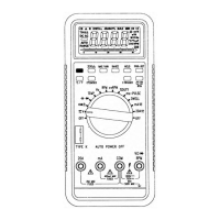
Meter Functions
-
RPMIXI ORPM
/
Meter Functions
-
Duty Cycle
(%)
Getting Started
3
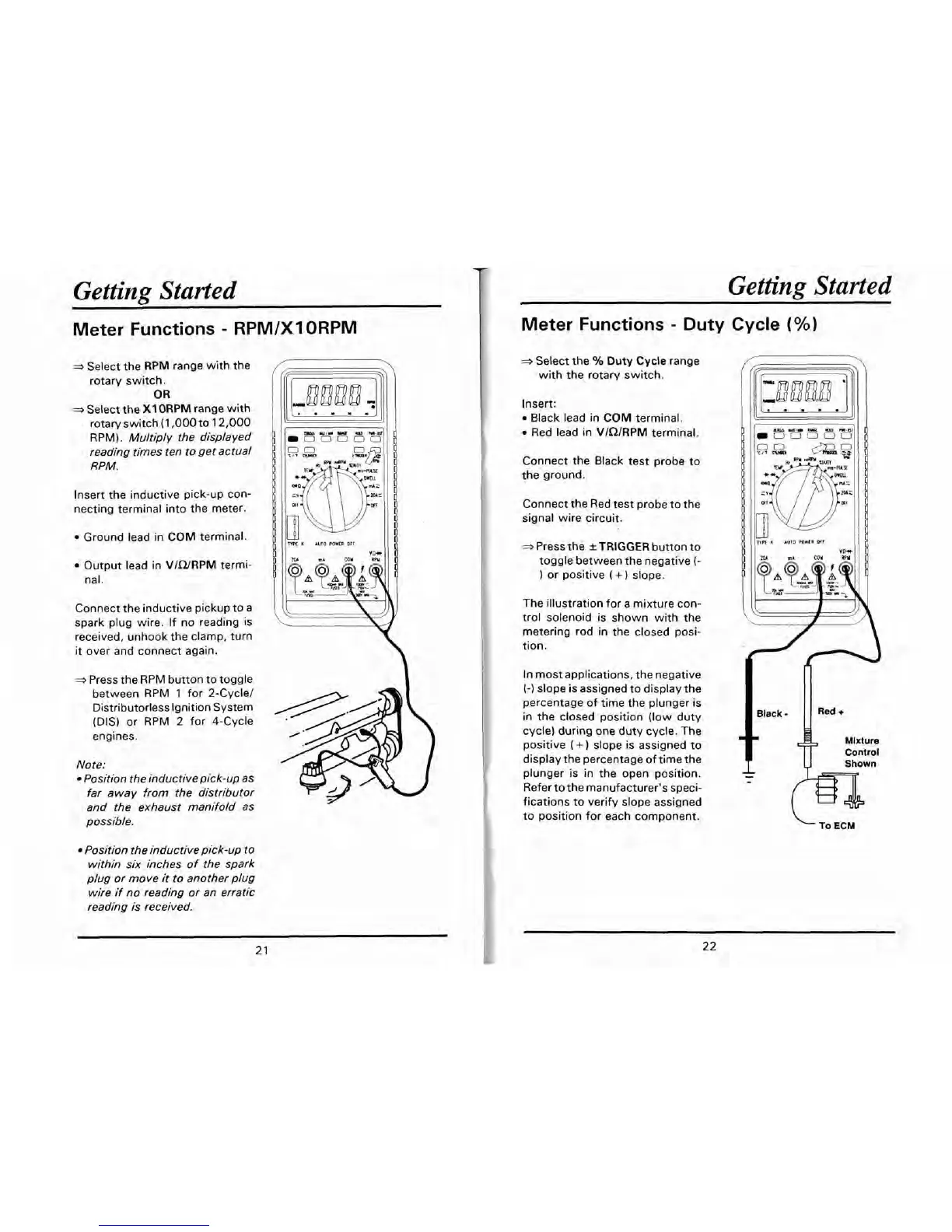
Select the RPM range with the
rotary switch.
OR
3
Select the
X1
ORPM
range with
rotary switch (1,000 to 12,000
RPM).
Multiply the displayed
reading times ten to get actual
RPM.
Getting Started
Insert the inductive pick-up con-
necting terminal into the meter.
Ground lead in
COM
terminal.
Output lead in
VICURPM
termi-
nal.
Connect the inductive pickup to a
spark plug wire. If no reading is
received, unhook the clamp, turn
it
over and connect again.
-
Press the RPM button to toggle
between RPM 1 for 2-Cycle1
Distributorless Ignition System
(DIS) or RPM
2
for 4-Cycle
engines.
Note:
Position the
inductive pick-up
as
far away from the distributor
and the exhaust manifold as
possible.
Position the inductive pick-up to
within six inches of the spark
plug or move it to another plug
wire if no reading or an erratic
reading is received.
K
AUTO
POWER
orr
*Select the
%
Duty
Cycle
range
with the rotary switch.
Insert:
Black lead in
COM
terminal.
Red lead in
VlQlRPM
terminal.
Connect the Black test probe to
the ground.
Connect the Red test probe to the
signal wire circuit.
*
Press the
*TRIGGER
button to
toggle between the negative
(-
or positive
(
+
)
slope.
The illustration for a mixture con-
trol solenoid is shown with the
metering rod in the closed posi-
tion.
In most applications, the negative
(-1
slope is assigned to display the
percentage of time the plunger is
in the closed position (low duty
cycle) during one duty cycle. The
positive
(
+
slope is assigned to
display the percentage of time the
plunger is in the open position.
Refer to the manufacturer's speci-
fications to verify slope assigned
to position for each component.
To
ECM