Basic Diagnostic Testing
Basic Diagnostic Testing
Ignition System Tests
Ignition System Tests Cont
'd..
.
[I]
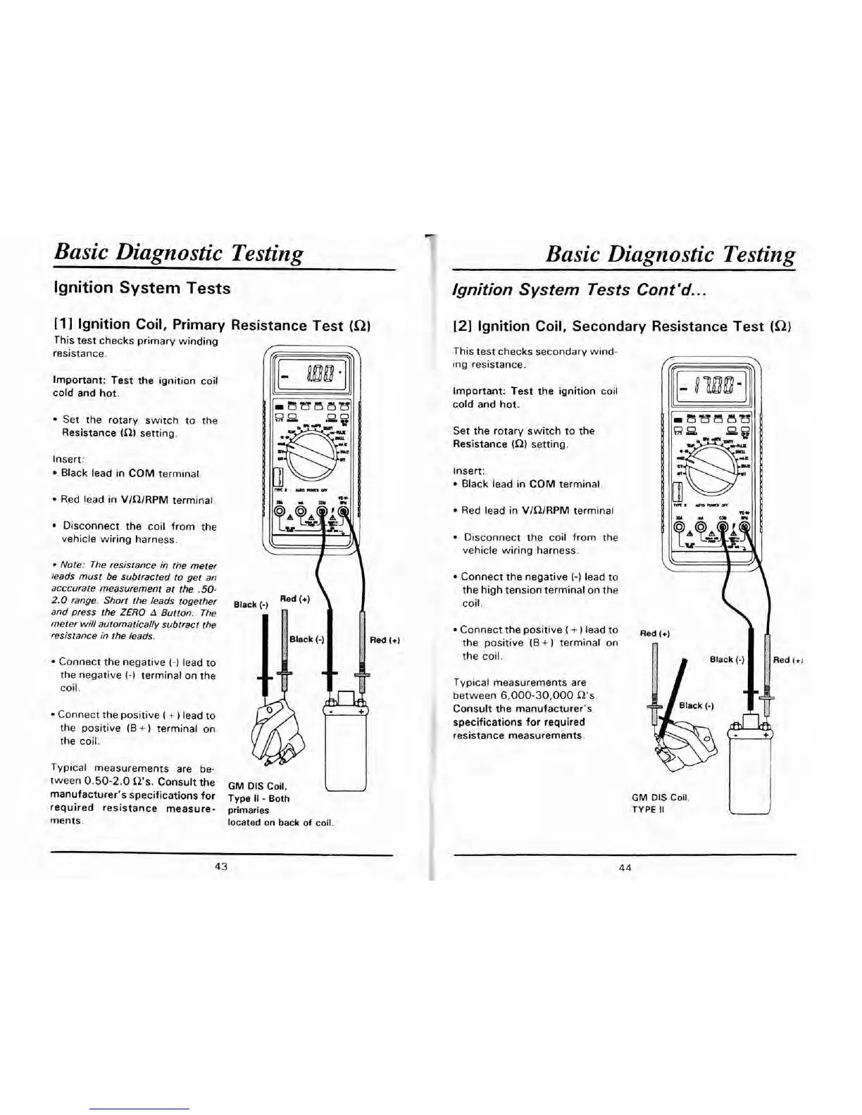
Ignition Coil, Primary Resistance Test
(a)
[2]
Ignition Coil, Secondary Resistance Test
(Q)
This test checks primary winding
resistance.
Important: Test the ignition coil
cold and hot.
Set the rotary switch to the
Resistance
(R) setting.
Insert:
Black lead in COM terminal
Red lead
in
VlQlRPM terminal
Disconnect the coil from the
vehicle wiring harness.
Note: The resistance in ti-te meter
leads must be subtracted to get an
acccurate measurement at the
.50-
2.0
range. Short the leads together
and press the
ZERO
A
Button. The
meter will automatically subtract the
resistance in the leads.
Connect the negative
(-1
lead to
the negative
(-1
terminal on the
coil.
Connect the positive
(
+
)
lead to
the positive
(B
+
terminal on
the coil.
Typical measurements are be-
tween
0.50-2.0
R's. Consult the
manufacturer's specifications for
required resistance measure-
ments.
Bla
Red
GM
DIS Coil,
Type
Il
-
Both
.u
primaries
located
on
back of coil.
This test checks secondary wind-
.-
.
ing resistance.
Important: Test the ignition coil
cold and hot.
Set the rotary switch to the
Resistance
(Q) setting.
Insert:
Black lead in COM terminal.
Red lead in VlRlRPM terminal.
Disconnect the coil from the
vehicle wiring harness.
Connect the negative
(-)
lead to
the high tension terminal on the
coil.
Connect the positive
(
+
)
lead to
the positive
(B
+
1
terminal on
the coil.
Typical measurements are
between
6,000-30,000
R's
Consult the manufacturer's
specifications for required
resistance measurements.
GM
DIS Coil.
TYPE
II
 Loading...