Basic Diagnostic Testing
lgnition System Tests Con t
'd..
.
[31
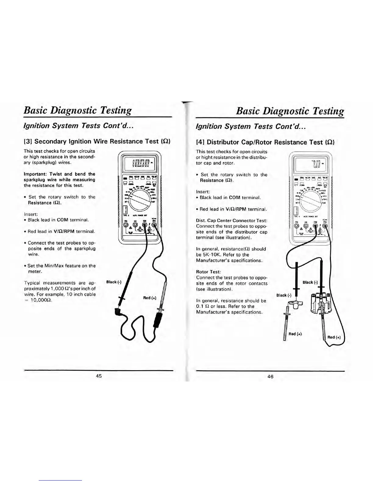
Secondary lgnition Wire Resistance Test
(Q)
This test checks for open circuits
or high resistance in the second-
ary
(sparkplug) wires.
Important: Twist and bend the
sparkplug wire while measuring
the resistance for this test.
Set the rotary switch to the
Resistance
(a).
Insert:
Black lead in COM terminal.
Red lead in VlnlRPM terminal.
Connect the test probes to op-
posite ends of the sparkplug
wire.
Set the MinJMax feature on the
meter.
Typical measurements are ap-
proximately
1,000
Q's per inch of
wire. For example,
10
inch cable
=
10,OOOQ.
Basic Diagnostic Testing
Ignition System Tests Cont
'd..
.
141
Distributor CapIRotor Resistance Test
(Q)
This test checks for open circuits
or hight resistance in the distribu-
tor cap and rotor.
Set the rotary switch to the
Resistance
(R).
Insert:
Black lead in COM terminal.
Red lead in VlQlRPM terminal.
Dist. Cap Center Connector Test:
Connect the test probes to oppo-
site ends of the distributor cap
terminal (see illustration).
In general,
resistance(L2) should
be
5K-1 OK.
Refer to the
Manufacturer's specifications.
Rotor Test:
Connect the test probes to oppo-
site ends of the rotor contacts
(see illustration).
In general, resistance should be
0.1 Q
or less. Refer to the
Manufacturer's specifications.
 Loading...