Atlas LCR45 User Guide January 2019 – Rev 4
Page 11
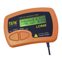
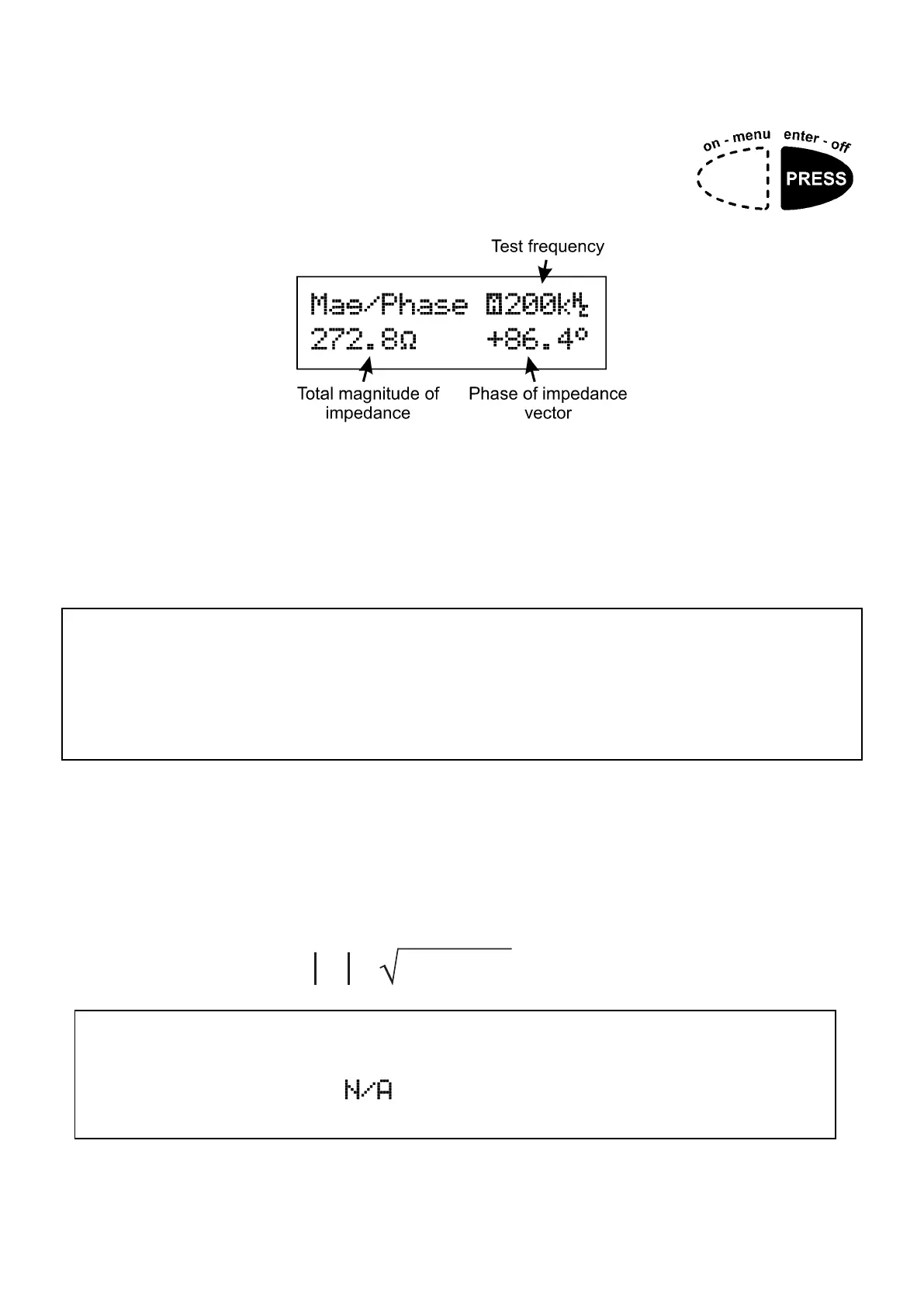
Magnitude and Phase Display
Pressing enter-off again will take you to a different
representation of the component’s impedance, the
Magnitude and Phase display.
This display is useful for gauging how close your component is to a
theoretical “ideal” inductor, capacitor or resistor.
Ideal capacitor: -90° phase
Ideal inductor: +90° phase.
Ideal resistor: 0° phase.
It is perfectly normal to see phase values that suggest the component is not
“ideal”. Even a small loss in an inductor can have significant influence on
the measured phase. Additionally, measurement resolution (particularly at
the edges of the LCR45 measurement ranges) can result in non-ideal phase
values.
The example shown above illustrates a component that is largely inductive at
the test frequency used.
Remember that the magnitude of the impedance is the Pythagorean addition of
the real and imaginary parts of the component’s impedance (not the arithmetic
sum).
Z =
Ohms
2 2
Note that it is not possible to display the magnitude and phase of
impedance if the test frequency is set to DC (either automatically or
manually). You will see on the magnitude and phase screen when
testing at DC.
 Loading...