Atlas LCR45 User Guide January 2019 – Rev 4
Page 9
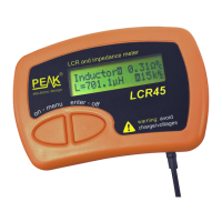
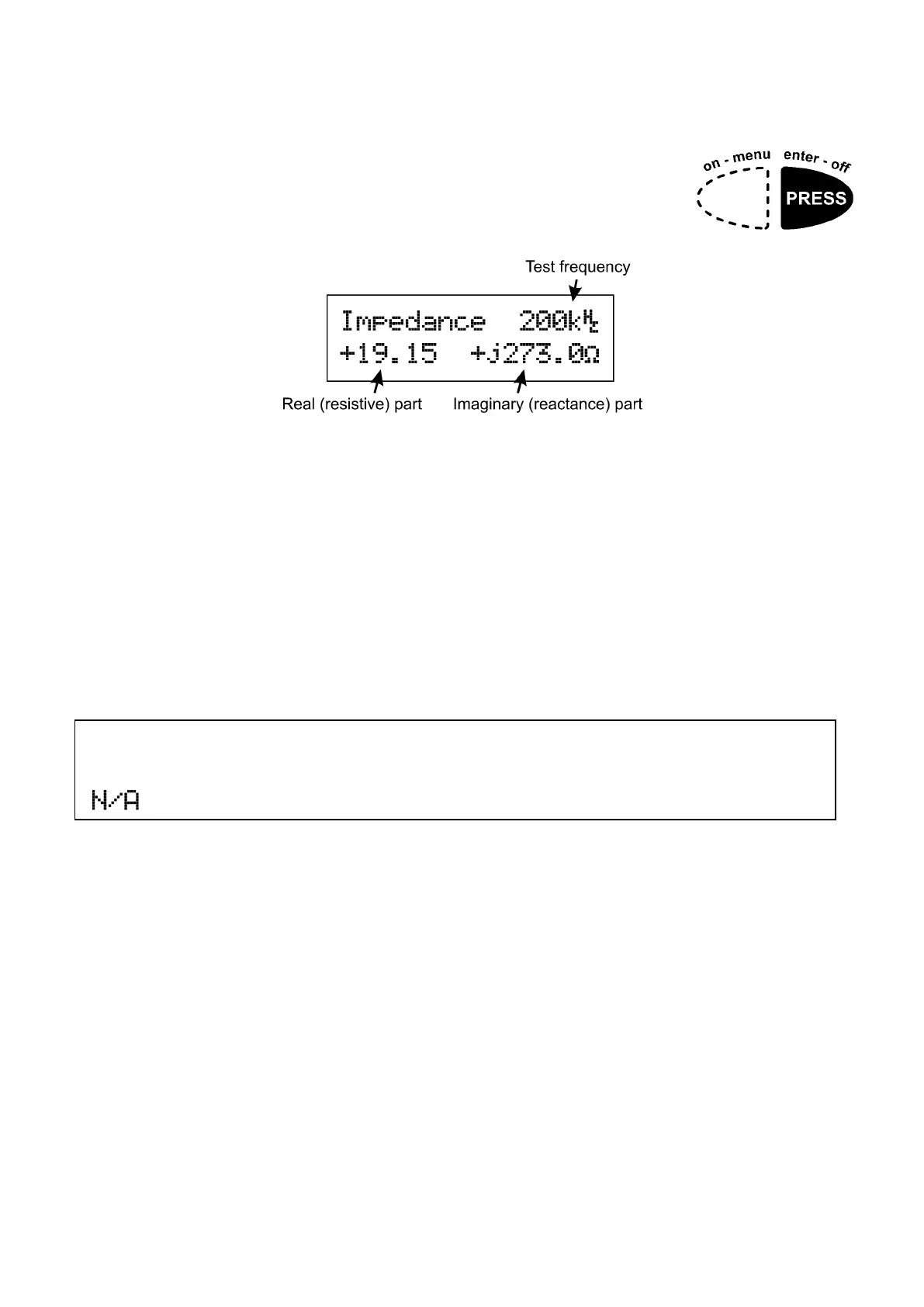
Impedance Display
While measurements are being made, you can switch to a
different display mode by pressing enter-off for further
information about the component’s impedance at the
current test frequency.
This is displayed as a complex number, comprising of a real (resistive) part
and an imaginary (reactive) part that is prefixed with j.
The complex number displayed can be very useful if you want to use the
impedance of your component in some other calculations. Remember that
most spreadsheet packages can deal directly with complex numbers and
therefore open up all manner of possibilities for using the true complex
impedance of your component. Impedance, when in complex number form,
can be used in the same way as simple resistance when dealing with series,
parallel or series/parallel networks.
Note that it is not possible to display complex impedance if the test
frequency is set to DC (either automatically or manually). You will see
on the impedance screen when testing at DC.
How the LCR45 uses Reactance
For inductors, you will generally see a positive imaginary (reactance) number.
The LCR45 calculates inductance from that reactance figure. Reactance of an
inductor is 2πfL.
Calculating the inductance from its reactance figure enables the LCR45 to
reduce the influence of winding resistance on readings.
The real part of the impedance display will largely consist of the DC winding
resistance but the figure may be different to the measured DC resistance. This
is because other aspects of the inductor (such as core losses) will influence the
real part of the impedance at frequencies other than DC. Core losses cannot
normally be seen at DC.
 Loading...