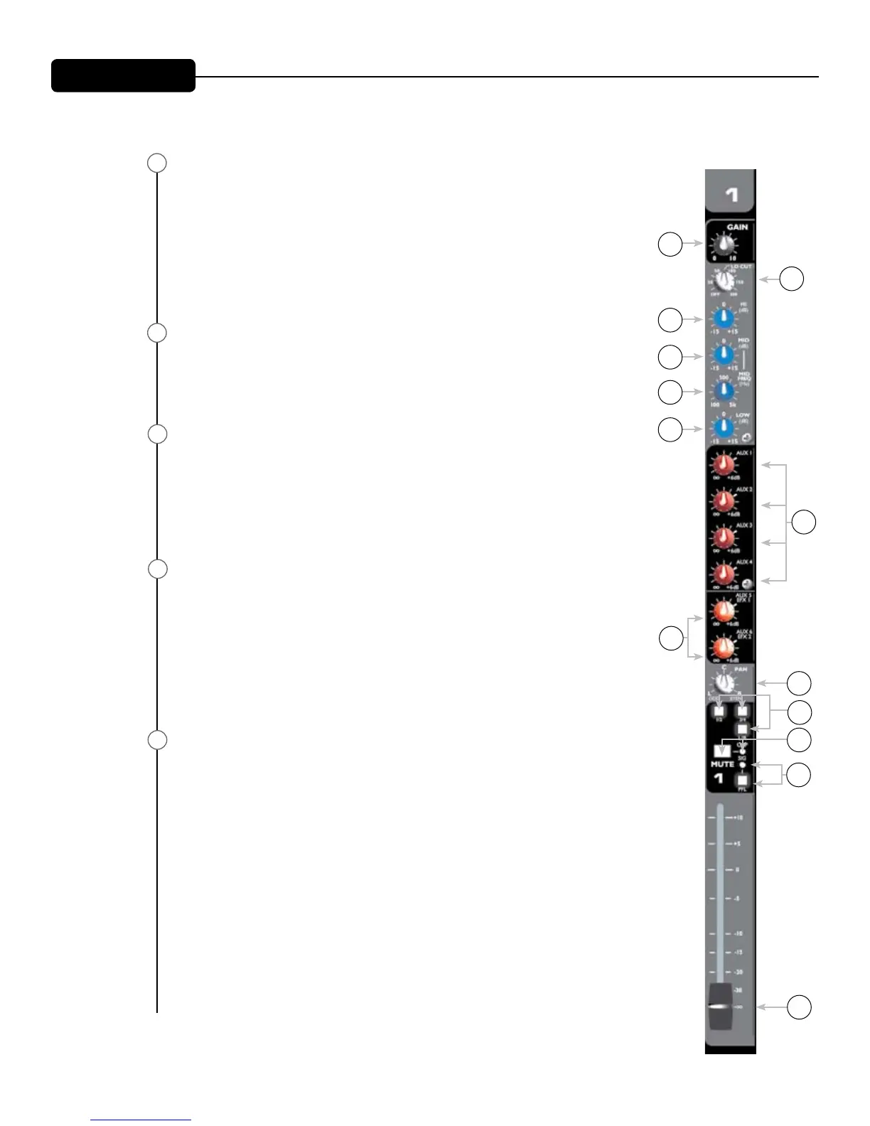
Pan
This control determines the signal’s position with respect to the assigned
L/R and Group 1–4 buses. Rotating the control counterclockwise increases
the amount of signal sent to L and odd-numbered groups; rotating clock-
wise increases the amount sent to R and even-numbered groups. For ex-
ample, with the channel Bus Assign switch (10) in the 1/2 position, rotating
the control counterclockwise increases the amount of signal sent to Group
1, while rotating clockwise increases the amount sent to Group 2. The C
position sends equal amounts to each.
1/2, 3/4, L/R Bus Assign Switches
These post-fader switches determine where the channel signal is being
sent. For example, to send a signal to Groups 1 & 2, depress the 1/2 button.
The PAN control (9) determines the signal level that is sent to each signal
bus.
Mute Switch/Mute-Clip LED
This switch mutes all Aux, Group and L/R sends from the corresponding
channel. This switch is equipped with a red LED that will illuminate when
the channel is muted. When the MUTE button is out, the LED functions as a
Clip indicator that will illuminate at 2 dB below clipping. Muting the channel
does not prevent the PFL signal from being sent to the PFL/AFL mix when
the PFL Switch (12) is in.
PFL Switch/Signal-PFL LED
This switch connects the channel’s pre-fader signal to the PFL/AFL mix.
When the PFL button is in, the channel’s signal can be monitored through
the headphones and/or on the PFL/AFL display. A yellow LED in the Mas-
ter section will blink to indicate that the signal on the Master LED display
and at the headphone output is PFL. Selecting PFL allows the operator to
monitor a channel even with the channel muted, and is especially useful for
cuing CDs/tapes. When the PFL button is out, the yellow channel LED will
function as a signal presence indicator (-20 dBu).
Channel Fader
This control varies the signal level from -∞ to +10 dB and sends the signal
from the channel to the L/R and Group buses and to the Effects Sends. The
optimum setting is the ø (unity gain) position.
Front Panel
9
10
11
13
12
2
3
4
6
5
1
8
7
9
10
11
12
13
 Loading...