6
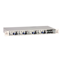
1. INPUT TRIM: This control adjusts the gain of the input preamplifier, which sets the operating level for the channel.
We recommend that the gain be adjusted so that ringing does not occur with the channel’s mix level control
set to maximum. The signal present LED (green) should be lit most of the time and the clip LED (red) should
never light. If the channel mix control is typically below the 12 o'clock position, the gain can be lowered
further to make mix adjustments simpler. The channel level can be checked by engaging the PFL button and
observing the signal on the meter and in the headphones. This control can be adjusted with your fingers but
is recessed to prevent accidental adjustment.
2. SIGNAL/MUTE/CLIP LED: This light tells three stories. It illuminates green when the channel signal level exceeds
–20 dBu, giving a quick visual indication that audio is present in the channel. If the signal level nears the
overload point, it flashes red, warning that gain should be reduced. If the mute switch is pressed, it lights red
continuously to indicate that the channel is off.
3. WIRELESS/PULPIT PRIORITY ASSIGNMENT: When a person speaks into a mic connected to the S-4, the
Automix
™
circuitry reduces gain of other channels with lower signal levels. If the signal level is the same on
two channels, each channel gets the same gain if their priority is the same. However, when a person wearing
a wireless microphone walks near another microphone that is on, the resulting interference, called comb
filtering, can hinder intelligibility and cause distraction. Setting this switch to the wireless position (high
priority) gives the channel dominance over pulpit priority
inputs and wireless priority inputs with a lower signal
level. (A wireless microphone should have precedence
over a fixed podium microphone to reduce the comb
filtering effects that occur when both pick up the same
source.) For applications such as meetings and panel
discussions, the moderator or main speaker can have
priority even if he/she is not using a wireless microphone.
4. 75 Hz/150 Hz LOW-CUT FILTER: The low-cut filter switch
selects 75 Hz or 150 Hz for the low cut filter frequency.
The filter slope was intentionally chosen to be 12
dB/octave so it can also be used for equalization. This filter
can help reduce microphone stand and handling noise and
also reduce the proximity effect.
5. COMPRESSOR THRESHOLD: Each channel has a built-in soft-knee compressor to help keep loud voices from
getting out of control. This control sets the point where compression begins. When the amount of gain
reduction exceeds 3 dB, the red LED beside it illuminates. To set this control, begin at the maximum position
and turn it counterclockwise to the point where the LED lights only on loud peaks. If the LED blinks most
of the time, the threshold should be raised. If compression is not required, set this control to maximum (off).
6. Mid Morph
™
EQ: Where most midrange controls work at just one frequency, Mid Morph works at two. When
turned counterclockwise, it reduces the volume of low/mid frequencies to reduce muddiness. When turned
clockwise, it boosts high/mid frequencies to add intelligibility to vocals. Either way, improved vocal or
instrument definition can be achieved.
7. STATUS/PFL: This light is green when the channel is active and is a dominant Automix channel. It will also light green
if the channel is in manual mode. If it is not lit, it does not mean that the channel is off, but that the level is
being attenuated. The light will change color to red when the PFL switch is pressed, showing that this channel
has been assigned to the PFL monitoring bus.
1
2
3
4
5
6
7

 Loading...