9
Base Frame 3-Pt Hitch Installation
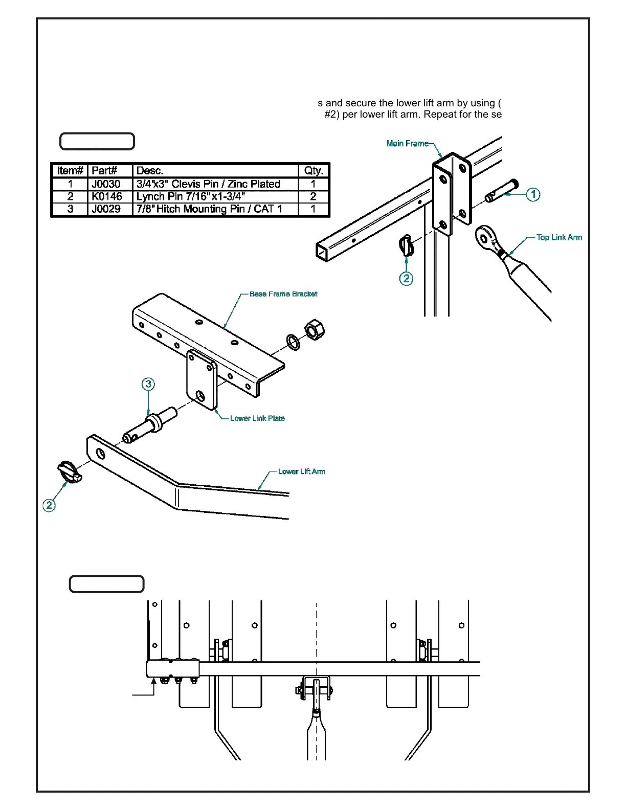
Raise the Main Frame Assembly until the Mounting Bracket of the Main Frame Assembly aligns with the top link arm.
Secure the top link hitch socket using (1) 3/4” x 3” Clevis Pin (Item #1) and (1) 7/16” x 1-3/4” Lynch Pin (Item #2).
Refer to Figure A.
Align the lower lift arm to the outside of the Lower Link Plates and secure the lower lift arm by using (1) 7/8” Hitch
Mounting Pin (Item #3) and (1) 7/16” x 1-3/4” Lynch Pin (Item #2) per lower lift arm. Repeat for the second lower lift
arm. Refer to Figure A.
Figure A
Figure B
NOTE: Some part features have been hidden
from view for visual clarity.
Check that the Main Frame Assembly is centered with the Top Link Arm and that the Top Link Arm is centered to
the tractor. Refer to Figure B.
Main Frame
Assembly
Center to Tractor
Mounting
Bracket
 Loading...