29
SIGNAL CONNECTIONS
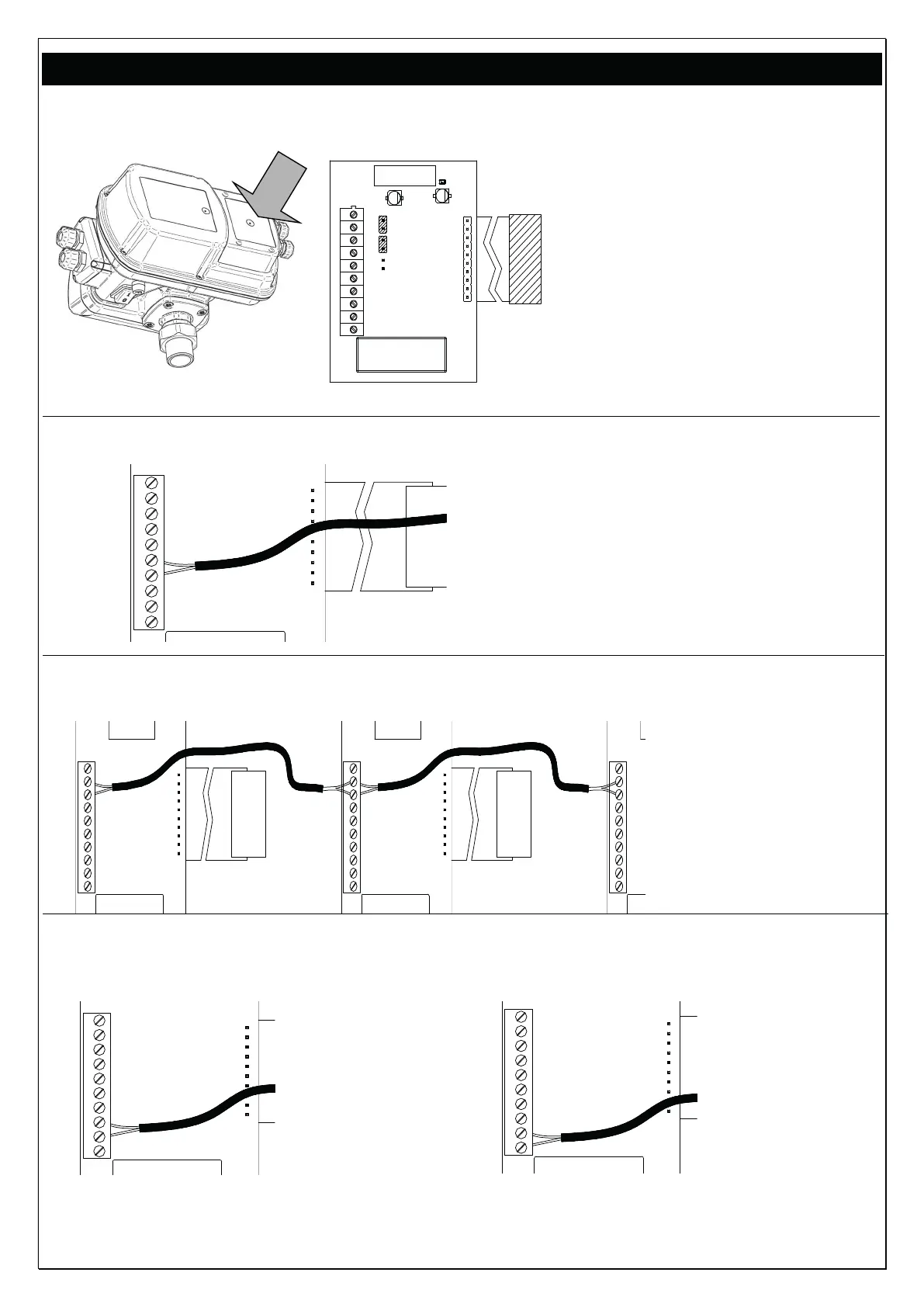
Expansion board: is located in the back of the inverter (see fig. below)
1
2
3
4
5
6
7
8
9
10
J P3
J P4
J P5
Terminal clamp operation description:
10: not connected
9: RS 485 +
8: RS 485 -
7: not connected
6: not connected
5: level input
4: GND
3: NC output signal
2: comune C
1: NO output signal
JP3: bridged, no function
JP4: bridged, no function
- LEVEL SIGNAL CONNECTION
10
9
8
7
6
5
4
3
2
1
(or other input signal)
Connect the signal cable to clamps
4 e 5
In applications with parallel inverters,
the wiring must be carried out on the
MASTER
- RS485 SIGNAL CONNECTION
10
9
8
7
6
5
4
3
2
1
10
9
8
7
6
5
4
3
2
1
10
9
8
7
6
5
4
3
2
1
Connect the terminals
n° 8 of the inverters in
parallel (RS 485 –)
Connect the terminals
n° 9 of the inverters in
parallel (RS 485 +)
as shown aside.
- ALARM SIGNAL CONNECTION
(In applications with parallel inverters, the wiring must be carried out on the MASTER)
10
9
8
7
6
5
4
3
2
1
Logic NC
(normally
closed)
Connect the
signal cable to
terminals 2 and 3
10
9
8
7
6
5
4
3
2
1
Logic NO
(normally
open)
Connect the
signal cable to
terminals 1 and
2
The maximum load for connection is 2 A at 250 Vac
 Loading...