ECP200 EXPERT
Pag. 19
USE AND MAINTENANCE MANUAL
Rev. 01-11
ALARM RELAY / RS485 SWITCHING
Open the front of the box as described in Chap. 2.3 (page 6): rotate it downwards 180° to
gain access to the electronic board.
Undo the 6 CPU board fixing screws: remove the board from the frontal part of the box in
ABS.
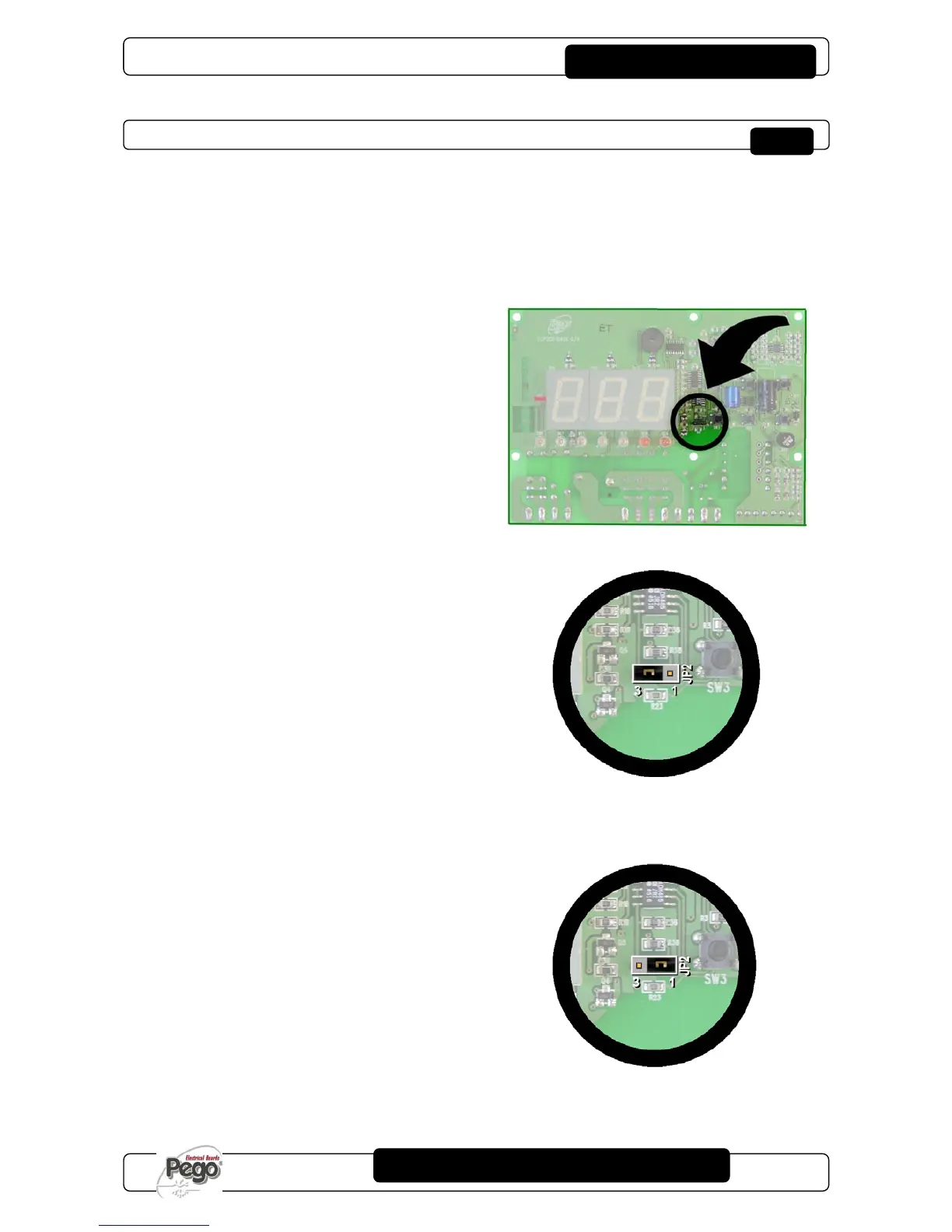
Configure the jumper from JUMPER JP2
(placed on the front of electrical board near
the display far down on the right) following
one of the ensuing options.
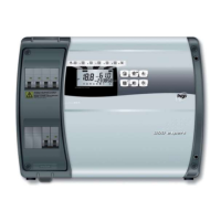
RS485 output selection:
Insert the jumper JP2 on 3-2 position and set
the 2
nd
level variable
AU=3 (TeleNET)
or
AU=7 (Modbus-RTU).
The connection clamps are RS485_(A) and
RS485_(B) on board of electrical board.
Remember besides to assign an univocal net
address in the current instruments net. (Ad
2
nd
level parameter).
Warning! with this configuration auxiliary relay
is disabled.
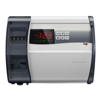
AUX/Alarm relay selection:
Insert the jumper JP2 in 2-1 position and set
the 2
nd
level variable AU to a value different
from 3 and 7 according to the needed
function. Clamps of configurable relay clean
contact are on AUX/ALL output, on board of
electronic board. Warning! with this
configuration RS485 connection is disabled.