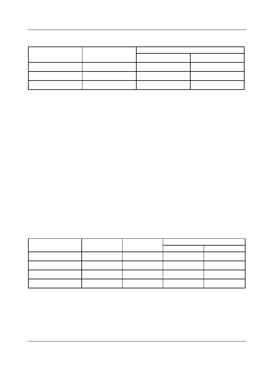
Trigger Indicators vs. Trigger Levels
Trigger Level
(manually set)
NOTE: This test must be performed in the
sequence given.
Recall the DEFAULT settings.
Press INPUT A and select MANual trigger
level, DC coupling, and
50 input
impedance.
Connect the LF synthesizer to Input A.
Use the following settings (into 50
):
Sine, 10 kHz, 0.9 Vpp, and +0.50 V DC.
Verify that the three modes for the
trigger indicator are working properly
by changing the trigger level:
Press the Trig key and enter +1 V via the
keyboard, then verify by pressing
EXIT/OK. Check the trigger indicator
according to Table 7-4.
Press the Trig key and enter 0.0 V via the
keyboard by pressing the
± key, then
verify by pressing EXIT/OK. Check the
trigger indicator according to Table 7-4.
— Press the Trig key and enter 0.5 V via the
keyboard, then verify by pressing
EXIT/OK. Check the trigger indicator
according to Table 7-4.
Apply the signal to Input B instead.
Press MEAS FUNC
Freq
Freq (A)
Press INPUT B and select MANual trigger
level, DC coupling and
50
input
impedance.
Repeat the trigger level settings above to
verify the three trigger indicator modes
for Input B.
USER MANUAL ● CNT 9x Series ● Rev.22 February 2020