Two-Channel
Measurements
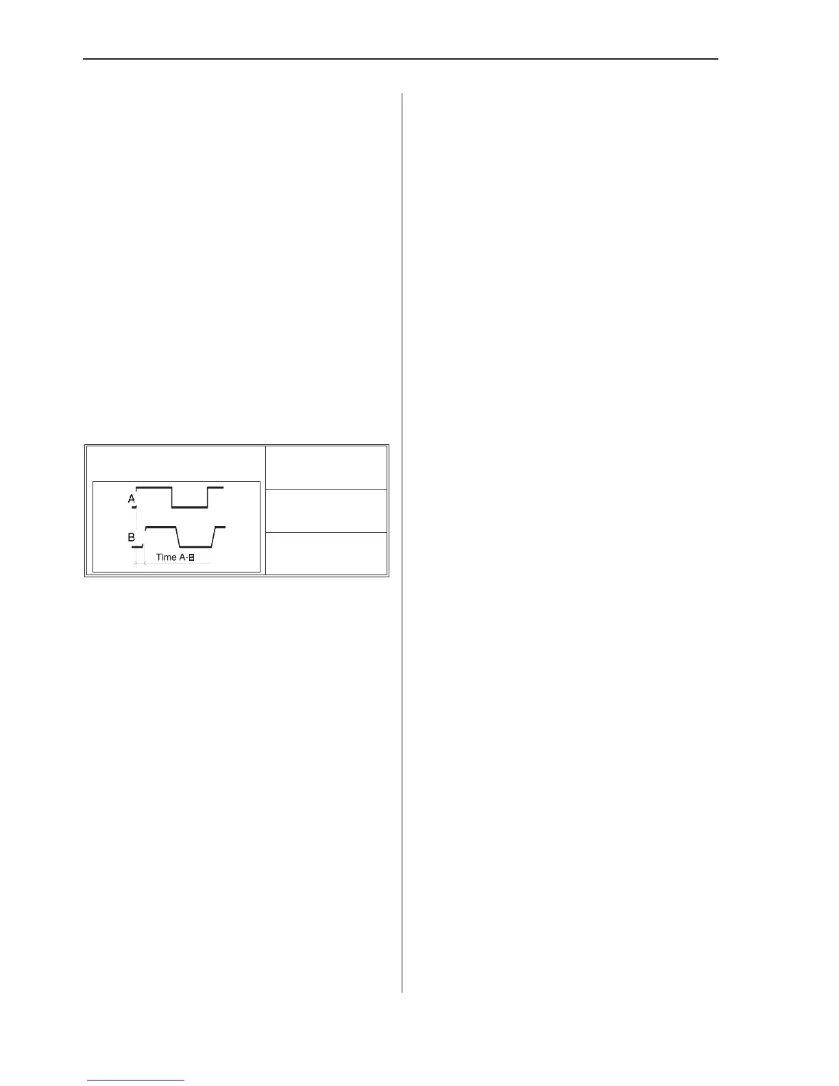
The counter can measure the timing relationship
between two channels with the Time Interval
AtoBand Phase A rel B functions.
Time Interval
Often function generators have a TTL output in
addition to the main output. We will make use of
this now. Connect a BNC cable from the TTL
output to Input A on the counter and another
BNC cable from the main output on the function
generator to Input B.
Set up the counter: Trigger Level:
AUTO
Function:
TIME INT A-B
Coupling: DC
(both A and B)
You can now read the time difference between
the TTL and main outputs of the generator.
Phase
So far the counter has shown the timing rela
-
tionship between the TTL and the main output
of the generator as a time delay. You can also
show this as phase shift between the signals.
n
Using Auto to set fixed trigger
levels (Auto Once)
Some measurements like Phase A rel B ben
-
efit from having fixed trigger levels. This is
because a change in trigger level causes a
change in the measured phase shift, and Auto
might change the trigger level between mea
-
surements.
To avoid calculating the trigger levels yourself,
you can let the counter measure the Auto levels
and then store them as fixed values.
Press INPUT A and check that Auto is still se
-
lected. Read the Auto trigger level for Input
A. Select Man. Note that the automatically
calculated trigger level is now entered as a
fixed manual level.
Press INPUT B and run through the same
steps once more to store this level as a manu
-
ally set trigger level as well.
n
Procedure
Use the MEAS FUNC key to select Phase A
rel B. Now the channel delay is expressed as
phase shift in degrees.
Increase the frequency of the generator to
2 kHz, 20 kHz, 200 kHz, 2 MHz, and
20 MHz. Watch the phase difference change.
Memory Settings
See also page 3-8.
The counter has 20 memory locations in
which you can store frequently used instru
-
ment settings.
–
To save an instrument setting, press the
USER OPT key.
–
Select the Save/Recall key.
–
Press Save Current Setup, and select
one of the memory locations using the
LEFT/RIGHT arrow keys. Note that the
first ten positions may be user-protected.
–
Press EXIT/OK three times to return to the
normal display mode.
–
Now change some settings on the counter,
and repeat the first steps above, until you
have pressed Save/Recall.
Exercises
4-6 Two-Channel Measurements
 Loading...


