Fig. 3-1 Block diagram of the signal conditioning
Fig. 3-2 Input settings menu.
4.1.1. Impedance
The input impedance can be set to 1 MΩ or 50 Ω by toggling the corresponding softkey.
CAUTION: Switching the impedance to 50 Ω when the input voltage is
above 12 Vrms may cause permanent damage to the input circuitry.
4.1.2. Attenuation
The input signal’s amplitude can be attenuated by 1 or 10 by toggling the softkey marked 1x/10x. Use attenuation
whenever the input signal exceeds the dynamic input voltage range ±5 V or else when attenuation can reduce the
influence of noise and interference. See the section dealing with these matters at the end of this chapter.
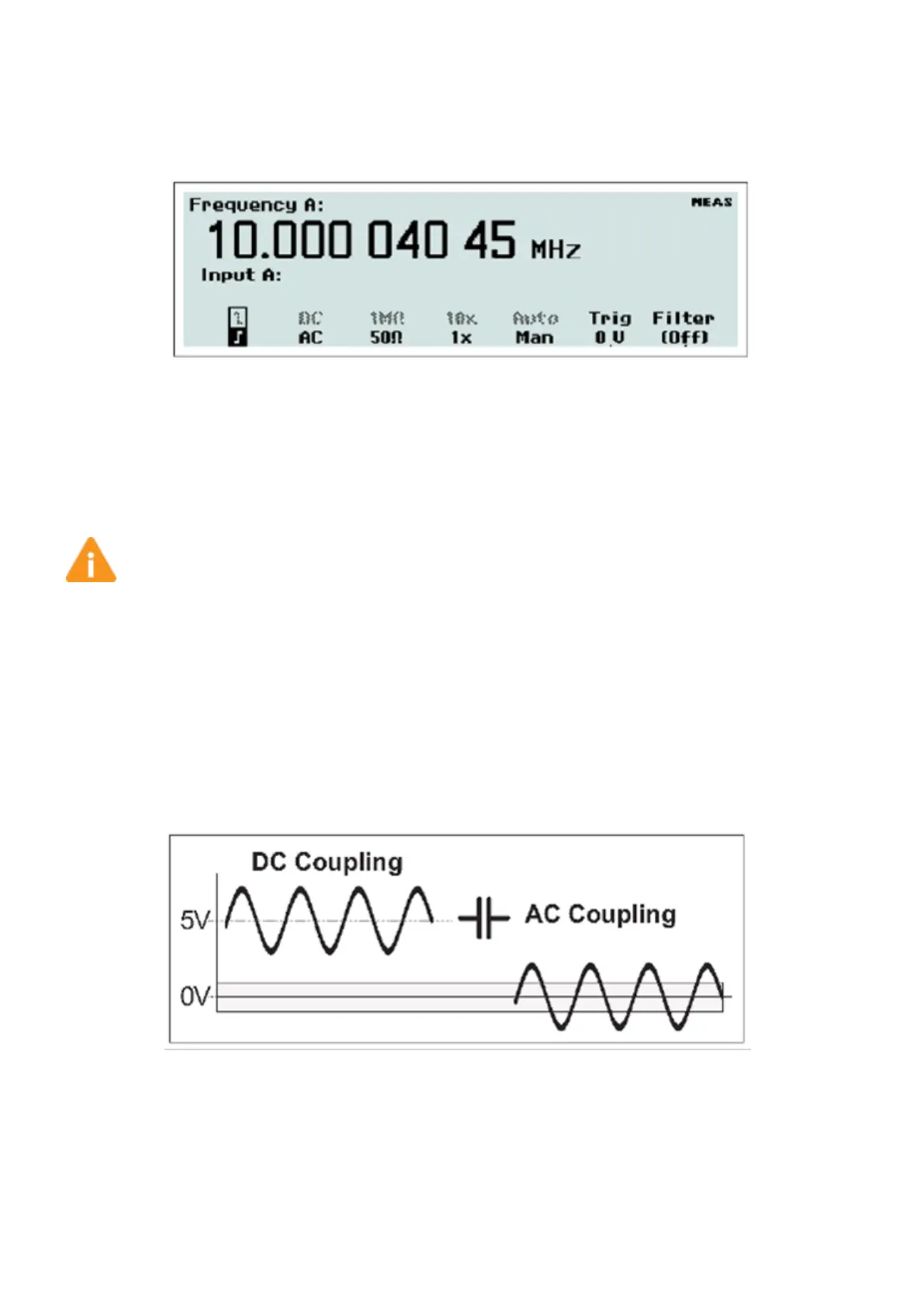
4.1.3. Coupling
Switch between AC coupling and DC coupling by toggling the softkey AC/DC.
Fig. 3-3 AC coupling a symmetrical signal.
Use the AC coupling feature to eliminate unwanted DC signal components. Always use AC coupling when the AC signal
is superimposed on a DC voltage that is higher than the trigger level setting range. However, we recommend AC
coupling in many other measurement situations as well.
41 / 50