Fig. 3-13 shows that less noise still affects the trigger point by advancing or delaying it, but it does not cause erroneous
counts. This trigger uncertainty is of particular importance when measuring low frequency signals, since the signal slew
rate (in V/s) is low for LF signals. To reduce the trigger uncertainty, it is desirable to cross the hysteresis band as fast as
possible.
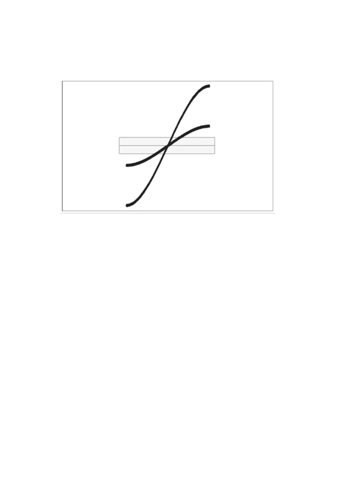
Fig. 3-14 Low amplitude delays the trig¬ger point
Fig. 3-14 shows that a high amplitude signal passes the hysteresis faster than a low amplitude signal. For low frequency
measurements where the trigger uncertainty is of importance, do not attenuate the signal too much, and set the
sensitivity of the counter high.
In practice however, trigger errors caused by erroneous counts (Fig. 3-10 and Fig. 3-12) are much more important and
require just the opposite measures to be taken.
To avoid erroneous counting caused by spurious signals, you need to avoid excessive input signal amplitudes. This is
particularly valid when measuring on high impedance circuitry and when using 1 MW input impedance. Under these
conditions, the cables easily pick up noise.
External attenuation and the internal 10x attenuator reduce the signal amplitude, including the noise, while the internal
sensitivity control in the counter reduces the counter’s sensitivity, including sensitivity to noise. Reduce excessive signal
amplitudes with the 10x attenuator, or with an external coaxial attenuator, or a 10:1 probe.
4.2.2. How to use Trigger Level Setting
For most frequency measurements, the optimal triggering is obtained by positioning the mean trigger level at mid
amplitude, using either a narrow or a wide hysteresis band, depending on the signal characteristics.
48 / 50