A52x Series Refrigeration Controller with Adaptive Defrost Installation Instructions
6
Sensor Wiring
See Table 3 on page 7 for information about wire gauge and maximum sensor wire length. See Table 12 and
Table 13 on page 11 for the sensor technical specifications.
Observe the following guidelines when you wire sensors to the A52x Controller:
• Sensor leads are not color coded or polarity-specific; you can connect either of the two sensor leads to the Sn1
or Sn2 terminal and a C terminal.
• Select only the sensor that is designed to operate in the ambient operating range that your A52x Controller is
intended to monitor and control.
• Keep the sensor leads as short as possible in your application. The additional resistance in long sensor cables
can create an offset between the actual temperature and the displayed temperature. Solder or butt splice
connections are recommended.
Use 0.30 mm
2
(22 AWG), stranded-wires and twisted-leads cable with a cable shield for extending sensor cable
runs.
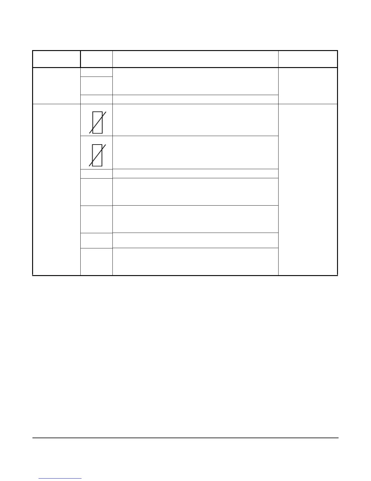
Table 2: A52x Controller Low-Voltage Terminal Blocks, Terminals, and Wire Sizes
Terminal
Block Label
Terminal
Label
Description, Function, and Requirements Recommended
Wire Sizes
RS485
MODBUS
A + The RS485 Modbus communications terminal block provides a
restricted connection to the Modbus connections on an optional
Precision Superheat Controller (PSHC). Do not connect any other
Modbus device to these terminals.
0.20 to 0.30 mm
2
(26 to 22 AWG)
Stranded wires and
twisted-leads cable
B -
REF RS485 Modbus signal common or reference
ANALOG
INPUT/OUTPUT
Sn1 The main space temperature sensor. Connect either lead from the
sensor to Sn1. Connect the other lead to a Common (C) terminal.
Note: Sensors for A52x Controller are not polarity sensitive.
0.30 to 1.50 mm
2
(22 to 16 AWG)
Stranded wires and
twisted-leads cable
Sn2 Evaporator temperature sensor. Connect either lead from the
sensor to Sn2. Connect the other lead to a C terminal.
Note: Sensors for A52x Controller are not polarity sensitive.
Sn3 Not available
UI 4 Universal Input 4 can be configured as a 0–10 VDC analog input
or dry contact binary input. Connect a 0 to 10 VDC input or binary
input to the UI4 (+) terminal and a C (common/-) on the low voltage
terminal block.
UI 5 Universal Input 5 can be configured as a 0–10 VDC analog input
or dry contact binary input. Connect a 0 to 10 VDC input or binary
input to the UI5 (+) terminal and a C (common/-) on the low voltage
terminal block.
C Three low-voltage common terminals
All low-voltage C terminals are connected together.
AO1 Note: Analog Output 1 (AO1) is not supported in the A525. Make
no connection to this terminal. The A524 Controller does not
include an analog output and does not have an AO1 terminal
block.

 Loading...