A52x Series Refrigeration Controller with Adaptive Defrost Installation Instructions
7
1. At the listed cable lengths, there is less than 0.6°C (1°F) error between the temperature sensed at the A99B sensor and the
temperature displayed on the LCD.
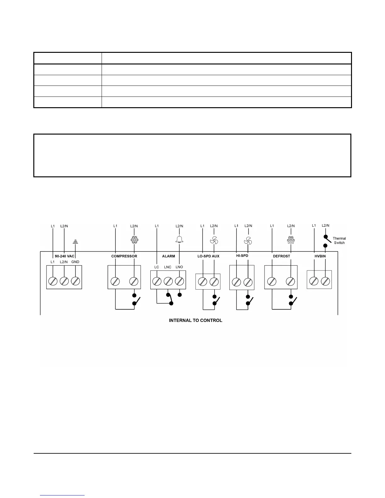
High-Voltage Wiring
Figure 5 on page 7 and Table 4 on page 8 describe the high-voltage wiring terminal blocks, wiring terminal labels,
and wire sizes. See Table 5 on page 8 to Table 9 on page 9 for relay electrical ratings.
Table 3: Maximum Recommended Sensor Cable Lengths and Wire Sizes
Wire Gauge
Maximum Sensor Cable Length
1
1.3 mm
2
(16 AWG)
150 m (500 ft)
0.82 mm
2
(18 AWG)
100 m (300 ft)
0.52 mm
2
(20 AWG)
60 m (200 ft)
0.33 mm
2
(22 AWG)
40 m (125 ft)
IMPORTANT: When connecting sensors with shielded cable to a control, connect the cable shield drain lead to
one of the C (common) terminals on the input sensor terminal block. Do not connect the shield at any other point
along the cable. Isolate and insulate the shield drain at the sensor end of the cable. Connecting a cable shield at
more than one point can enable transient currents to flow through the sensor cable shield, which can cause
erratic control operation.
Figure 5: A52x Controller High Voltage Terminal Block Connections

 Loading...