PB_P216_11 2016
4
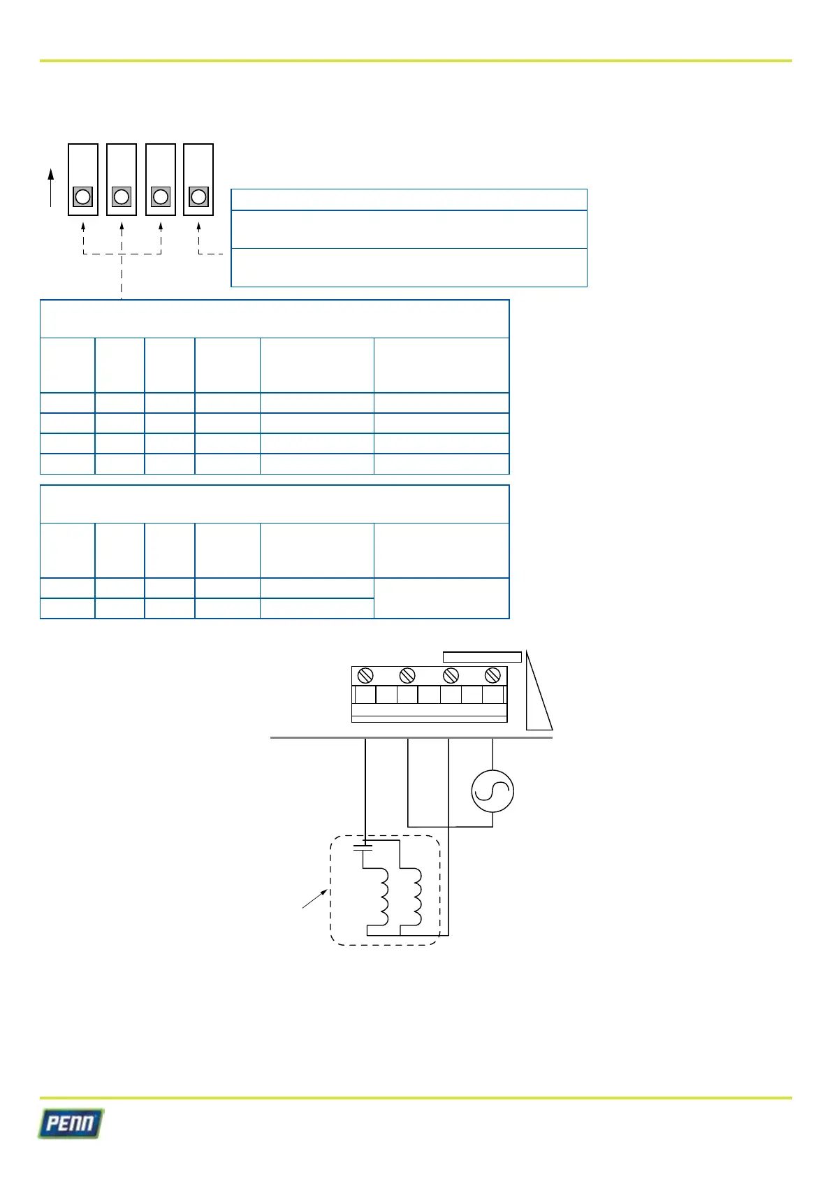
DIP switch settings and wiring diagram
Min speed switch
ON =
Motor never stops, always runs at min speed or
greater, depending on conditions.
OFF =
Minimum speed feature is disabled.
Motor shuts completely off at low pressure
P216 operation
using P499VCS-405C transducers
SW1 SW2 SW3 Mode
Setpoint range
CCW - CW
(BAR)
Proportional band
(BAR)
OFF OFF OFF Master 4 - 10 2,0
OFF ON OFF Master 8 - 14 2,5
ON OFF OFF Master 14 - 24 4,0
ON ON OFF Master 22 - 42 5,0
P216 operation
in slave mode
SW1 SW2 SW3 Mode
Setpoint range
CCW - CW
(Vdc)
Proportional band
(BAR)
OFF OFF ON Slave 2 - 10 Vdc
(See Note 1)
OFF ON ON Slave 1 - 5 Vdc
Note 1: The proportional band in slave mode extends from 0 Vdc to the setpoint voltage
TB1
M1 L1 L2/N L2/N
VAC
When switch 3 is set to ON, the slave mode is selected and the setpoint potentiometer denes the input voltage level that
causes the motor to run at full speed.
For example:
• If the 2–10 Vdc setpoint range is selected and the setpoint potentiometer is adjusted completely to "+", then the motor
will run at full speed when Vin = 10 Vdc.
• If the setpoint potentiometer is adjusted midway between "-" and "+", then the motor will run at full speed when Vin = 6,0 Vdc
(see Figure 3).
1 2 3 4
ON
Power supply
208 - 240 Vac 50/60 Hz
Fan-motor