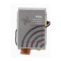
P66 Series Electronic Fan Speed Controls Installation Instructions 3
Mounting
Observe the following guidelines when mounting a
P66 control and routing the control’s capillary tube:
CAUTION: Risk of Environmental and
Property Damage.
Coil and secure excess capillary tubing away from
contact with sharp or abrasive objects or surfaces.
Vibration or sharp or abrasive objects in contact with
capillary tubes can cause damage that may result in
refrigerant leaks or loss of element charge, which
may result in damage to the environment or
property.
MISE EN GARDE: Risque de dommages
environnementaux et dégâts matériels.
Enrouler et fixer l'excédent de tubes capillaires de
manière à éviter tout contact avec des objets
coupants ou des surfaces abrasives. Des vibrations
ou des objets coupants ou abrasifs en contact avec
les tubes capillaires risque d'endommager ceux-ci et
d'occasionner des fuites de réfrigérant ou des pertes
de charge, susceptibles de provoquer des
dommages environnementaux ou des dégâts
matériels
CAUTION: Risk of Environmental and
Property Damage.
Avoid sharp bends in the capillary tubes. Sharp
bends can weaken or kink capillary tubes, which
may result in refrigerant leaks or restrictions of flow.
MISE EN GARDE: Risque de dommages
environnementaux et dégâts matériels.
Éviter de former des coudes serrés avec les tubes
capillaires. Les coudes serrés peuvent affaiblir les
tubes capillaires ou engendrer des pliures, ce qui
risque de provoquer des fuites de réfrigérant ou d'en
gêner l'écoulement.
• Maintain operating pressures and temperatures
within the listed product ratings to assure reliable
operation. See Technical Specifications table.
• Mount the P66 control away from sources of
excessive heat.
• Mount the P66 control with the cooling fins in a
vertical position with no obstruction preventing
airflow through the fins.
• Locate the P66 control where fan air passes
through the cooling fins to maximize heat
dissipation.
• Locate the P66 control so the pressure elements
inside the base are above the refrigerant liquid
level of the controlled equipment.
• Mount the control where it can be conveniently
wired to the power supply and the motor.
• Provide the recommended pressure connection in
the high-pressure vapor line near the condenser
inlet. (A 60 in. capillary is standard.)
• Evacuate all tubing and lines before connecting
the P66 control.
Note: A Schrader® valve depressor is provided with
the female flare fitting on standard P66 control models.
Wiring
WARNING: Risk of Electric Shock.
Disconnect the power supply before making
electrical connections. Contact with components
carrying hazardous voltage can cause electric shock
and may result in severe personal injury or death.
AVERTISSEMENT: Risque de décharge
électrique.
Débrancher l'alimentation avant de réaliser tout
branchement électrique. Tout contact avec des
composants conducteurs de tensions dangereuses
risque d'entraîner une décharge électrique et de
provoquer des blessures graves, voire mortelles.
WARNING: Risk of Electric Shock.
Ground the P66 Series Electronic Fan Speed
Control according to local, national, and regional
regulations. Failure to ground the P66 control may
result in electric shock and severe personal injury or
death.
AVERTISSEMENT: Risque de décharge
électrique.
Raccorder l' P66 Series Electronic Fan Speed
Control à la terre conformément aux réglementations
locales et nationales en vigueur. Le non-respect de
l'obligation de mise à la terre de l'P66 risque
d'entraîner une décharge électrique et de provoquer
des blessures graves, voire mortelles.

 Loading...