P66 Series Electronic Fan Speed Controls Installation Instructions 5
Setup and Adjustments
The P66 control’s throttling range is fixed and cannot
be adjusted. The operating range pressure is
adjustable within the control pressure range. See the
Technical Specifications table for P66 model pressure
ratings.
To adjust the operating range pressure:
1. Apply a reliable pressure gauge to the controlled
system to monitor the pressure adjustments.
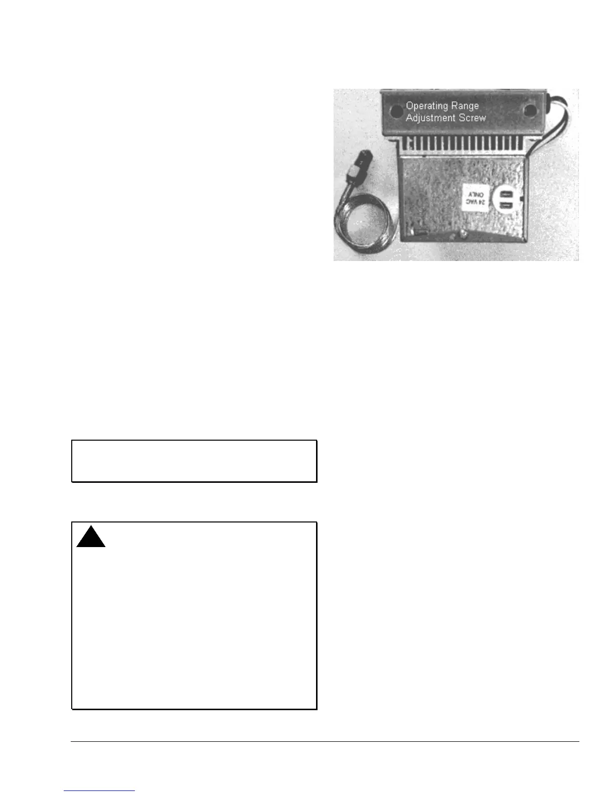
2. Access the operating range adjustment screw for
the P66 pressure transducer through the opening
in the upper left-hand corner of the P66 control
base (Figure 5).
Note: On dual pressure models, access to the
second adjustment screw is located in the lower right-
hand corner of the control base.
3. Turn the adjustment screw 1/2 turn (or less)
clockwise to increase the operating range
pressure or 1/2 turn (or less) counterclockwise to
decrease the operating range pressure.
• Low Pressure Models (80 to 200 psig):
1/2 turn = approximately ± 9 psig (62 kPa)
• Medium Pressure Models (140 to 350 psig):
1/2 turn = approximately ± 18 psig (124 kPa)
• High Pressure Models (300 to 500 psig):
1/2 turn = approximately ± 35 psig (241 kPa)
IMPORTANT: Do not adjust the operating range
screw more than 1/2 turn before allowing the system
pressure to stabilize.
4. Check system pressure and repeat Step 3 until
the desired operating range pressure is attained.
CAUTION: Risk of Property Damage.
Limit any adjustments to two full turns in either
direction. Over-adjustment may prohibit modulation
of the motor resulting in high head pressures. All
pressure adjustments should be verified with the use
of refrigerant pressure gauges.
MISE EN GARDE: Risque de dégâts matériels.
Limiter tout réglage à deux tours complets dans
chaque sens. Un réglage excessif risque
d'empêcher la modulation du moteur, engendrant
des pressions de refoulement élevées. Tous les
réglages de pression doivent être vérifiés à l'aide
des manomètres de refrigerant.
Figure 5: Operating Range Adjustment Screw
Location
Checkout
Before leaving the installation, observe working
application for correct operation. See the Operation
section for a typical operational sequence.
Operation
Condensing unit installation, operation, and
maintenance determine the overall capability of
maintaining a satisfactory pressure by means of fan
speed control. Within the operating range, the P66
control provides air delivery in direct proportion to heat
rejection requirements. This allows the refrigeration
system to perform efficiently in very low ambient
temperatures.
The P66 pressure transducer provides direct response
to changes in condenser pressure, regardless of the
variations in fan delivery curves. The dual input
models select the pressure input from the transducer
sensing the highest pressure.
See Figure 6 for a typical operational sequence for a
P66 control.
 Loading...