EasyManuals Logo

Penn P66AAB-1 User Manual

Penn P66AAB-1
9 pages
To Next Page IconTo Next Page
To Previous Page IconTo Previous Page
Page #2 background imageLoading...
Page #2 background image
2 P66 Series Electronic Fan Speed Controls Installation Instructions
Installation
!
WARNING: Risk of Personal Injury.
Do not install the P66 Series Electronic Fan Speed
Control in any application using corrosive or
flammable refrigerants. The P66 control is not
designed or intended for use with those refrigerants.
Use of the P66 control with corrosive or flammable
refrigerants may lead to the release of refrigerant,
which could cause property damage, fire, severe
personal injury, or death.
AVERTISSEMENT: Risque de blessure.
Ne pas installer l' P66 Series Electronic Fan Speed
Control dans une application utilisant des
réfrigérants corrosifs ou inflammables. L'P66 control
n'est pas conçu ou destiné à une utilisation avec de
tels réfrigérants. L'utilisation de l'P66 control avec
des réfrigérants corrosifs ou inflammables peut
entraîner une fuite de réfrigérant, qui risque de
provoquer des dégâts matériels, un incendie ou des
blessures graves, voire mortelles.
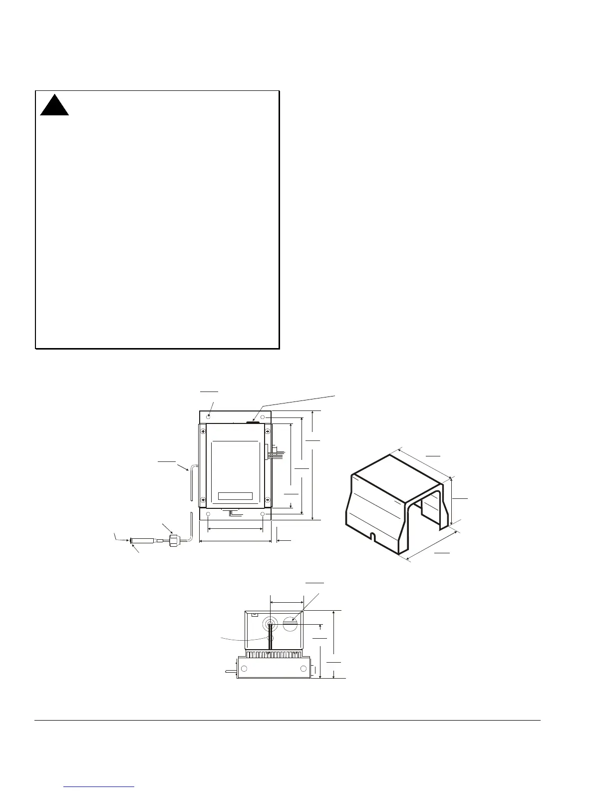
Dimensions
5.33
135
4.20
107
4.72
120
NEMA 3R Enclosure
4.12
105
3.34
85
0.875
22.23
Diameter
Conduit Hole
(2 places)
Two 22 AWG Wire
Leads for 24 VAC
Power Supply
(NEMA 3R
Enclosure)
1.28
33
6.75
172
6.00
152
5.26
134
3.38
86
4.56
116
0.27
7
Diameter Mounting Holes
for No. 10 Screw
0.218
5.54
Two 0.250 Spade Terminals
for 24 VAC Power Supply
Inside Plug (NEMA 1 Enclosure)
Valve
Depressor
1/4 in. Flare
7/16 in.
20 UNF-2B
0.093
2.36
Diameter
Capillary
P66_DIMS_ENCLOSURE
Figure 1: P66 Control and NEMA 3R Enclosure Dimensions, in. (mm)

Questions and Answers:

Question and Answer IconNeed help?

Do you have a question about the Penn P66AAB-1 and is the answer not in the manual?

Penn P66AAB-1 Specifications

Pressure Ratings IconPressure Ratings
control range (low pressure models)80 to 200 psig (552 to 1379 kPa)
control range (medium pressure models)140 to 350 psig (965 to 2413 kPa)
control range (high pressure models)300 to 500 psig (2048 to 3447 kPa)
effective throttling range (low pressure models)30 psi (207 kPa)
effective throttling range (medium pressure models)60 psi (414 kPa)
effective throttling range (high pressure models)90 psi (621 kPa)
maximum working pressure (low pressure models)200 psig (1379 kPa)
maximum working pressure (medium pressure models)350 psig (2413 kPa)
maximum working pressure (high pressure models)500 psig (3447 kPa)
maximum overpressure (low pressure models)250 psig (1724 kPa)
maximum overpressure (medium pressure models)400 psig (2758 kPa)
maximum overpressure (high pressure models)695 psig (4792 kPa)
Electrical Ratings IconElectrical Ratings
control voltage24 VAC, 1VA
line voltage range208 to 480 VAC
full load amperes (208 VAC)8.0
full load amperes (240 VAC)8.0
full load amperes (277 VAC)6.9
full load amperes (480 VAC)4.0
locked rotor amperes (208 VAC)16.5
locked rotor amperes (240 VAC)16.5
locked rotor amperes (277 VAC)14.3
locked rotor amperes (480 VAC)10.5
Operating Environment IconOperating Environment
maximum ambient temperature (208 VAC)130°F/54°C
maximum ambient temperature (240 VAC)130°F/54°C
maximum ambient temperature (277 VAC)130°F/54°C
maximum ambient temperature (480 VAC)150°F/66°C
minimum ambient storage temperature-40°F/-40°C (at all Voltages)
ambient storage temperature range-40°F/-40°C to 185°F/85°C

Related product manuals