EasyManuals Logo

Penn P66AAB-1 User Manual

Penn P66AAB-1
9 pages
To Next Page IconTo Next Page
To Previous Page IconTo Previous Page
Page #4 background imageLoading...
Page #4 background image
4 P66 Series Electronic Fan Speed Controls Installation Instructions
IMPORTANT: Use copper conductors only. Make all
wiring connections in accordance with the National
Electrical Code and local regulations. Do not exceed
the P66 Series Electronic Fan Speed Control’s
electrical ratings.
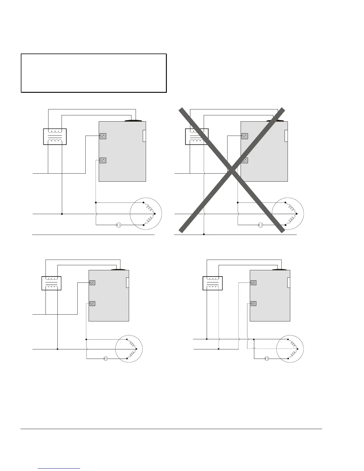
The P66 control must be supplied with 24 VAC (1 VA)
from an external transformer powered from the same
phase as the motor circuit (Figure 2, Figure 3, and
Figure 4). The low voltage input connections are 1/4
in. quick-connect terminals on the NEMA 1 models
and two 6 in. 22 AWG wires on the NEMA 3R models.
The line voltage connections are 10-32 screw
terminals.
Incorrect
Correct
L1
M1
Capacitor
Main
Aux
R
C
S
Motor
24
VAC
L1
L2
L3
P66
L1
M1
Capacitor
Main
Aux
R
C
S
Motor
24
VAC
L1
L2
L3
P66
P66_IN-PHASE_WIRRING
Figure 2: Permanent Split-Capacitor Motor Connections to the P66 Fan Speed Control
(The 24 VAC power supply must be connected in-phase with the motor power supply.)
L1
M1
Capacitor
Main
Aux
R
C
S
Motor
24
VAC
L1
L2
P66
P66_WIRING
Figure 3: Permanent Split-Capacitor Motor
Connections to the P66 Fan Speed Control
L1
M1
Capacitor
Main
Aux
R
C
S
Motor
24
VAC
L1
L2
P66
P66_WIRING_OPT
Figure 4: Optional Wiring Diagram for Permanent
Split-Capacitor Motor Connections to the P66
Fan Speed Control

Questions and Answers:

Question and Answer IconNeed help?

Do you have a question about the Penn P66AAB-1 and is the answer not in the manual?

Penn P66AAB-1 Specifications

Pressure Ratings IconPressure Ratings
control range (low pressure models)80 to 200 psig (552 to 1379 kPa)
control range (medium pressure models)140 to 350 psig (965 to 2413 kPa)
control range (high pressure models)300 to 500 psig (2048 to 3447 kPa)
effective throttling range (low pressure models)30 psi (207 kPa)
effective throttling range (medium pressure models)60 psi (414 kPa)
effective throttling range (high pressure models)90 psi (621 kPa)
maximum working pressure (low pressure models)200 psig (1379 kPa)
maximum working pressure (medium pressure models)350 psig (2413 kPa)
maximum working pressure (high pressure models)500 psig (3447 kPa)
maximum overpressure (low pressure models)250 psig (1724 kPa)
maximum overpressure (medium pressure models)400 psig (2758 kPa)
maximum overpressure (high pressure models)695 psig (4792 kPa)
Electrical Ratings IconElectrical Ratings
control voltage24 VAC, 1VA
line voltage range208 to 480 VAC
full load amperes (208 VAC)8.0
full load amperes (240 VAC)8.0
full load amperes (277 VAC)6.9
full load amperes (480 VAC)4.0
locked rotor amperes (208 VAC)16.5
locked rotor amperes (240 VAC)16.5
locked rotor amperes (277 VAC)14.3
locked rotor amperes (480 VAC)10.5
Operating Environment IconOperating Environment
maximum ambient temperature (208 VAC)130°F/54°C
maximum ambient temperature (240 VAC)130°F/54°C
maximum ambient temperature (277 VAC)130°F/54°C
maximum ambient temperature (480 VAC)150°F/66°C
minimum ambient storage temperature-40°F/-40°C (at all Voltages)
ambient storage temperature range-40°F/-40°C to 185°F/85°C

Related product manuals