System 450™ Series Control Modules with Analog Outputs Installation Instructions
8
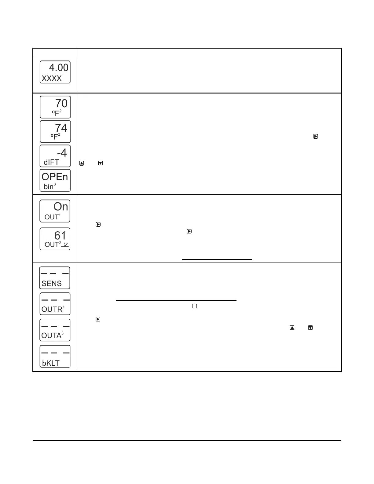
Table 3: System 450 Startup Screen, Main Screens, Status Screens, and Setup Start Screens Information
and Procedures
LCD Screen Name, Description/Function, User Action, and Example
Startup Screen: When you power on a System 450 control module, the LCD displays the control module’s
current firmware version for approximately five seconds before it displays the Main (Input Status) screen.
The screen example shows System 450 firmware version number 4.00 on the top of the screen. The
number on the bottom of the screen (indicated in this example with xxxx) identifies the Johnson Controls
firmware.
Main (Input Status) Screens: During normal operation, the Main screens automatically scroll through the
current status of each input sensor in your control system and display the sensor number, the unit of
measurement, and the sensed condition value.
Main screens are view-only; selections are not made in Main screens. The Main screens are the
System 450 default screens. After 2 minutes of inactivity in any screen, the UI returns to the Main
screens.
While the Main screens are scrolling, you can press any key to exit idle mode, then press
repeatedly to scroll through and view the System Status screens for all inputs and outputs in your
control system.
While the Main Screens are scrolling, you can press any key to exit idle mode, then press and hold
and for 5 seconds to access your control system’s Setup Start screens.
The top two screen examples show Sensor 1 sensing 70°F and Sensor 2 sensing 74°F. The third screen
example shows a Temperature Differential Sensor that is sensing a -4 degree differential. The bottom
screen shows Sensor 3 set up as a Binary Input and the input is open.
System Status Screens: The System Status screens display the current status of all inputs and outputs in
your control system. System Status screens are view-only; selections are not made in Status screens.
Relay output status screens display output number and relay status (On/Off). Analog output status screens
display output number, signal strength, and control ramp icon.
Press
repeatedly to scroll and view the System Status screens for the inputs and outputs in your
control system. When you stop pressing
, the displayed Status screen refreshes its value and
remains displayed for 2 minutes before returning to the Main Screens.
The screen examples show that the Output 1 relay is On and the signal strength of Output 3 is 61% of the
total signal strength. The control ramp icon in the bottom screen example indicates that the Analog Output
is set up with SP<EP and OSP<OEP. See Setting Up an Analog Output
for information about ramp icons.
Setup Start Screens: Setup Start screens are view-only screens from which you can access the setup
screens for the sensors, the displayed output, or the backlight brightness. The Sensor Setup Start screen is
the first screen displayed when you access the System 450 setup screens.
Note: The numerical order and type of Output Setup Start screens are determined by the modules that are
selected for your System 450 control system and their physical order in the control system module
assembly. See Setting Up a Control System in the User Interface on page 5 for more information.
From the Sensor Setup Start screen, press repeatedly to scroll through the Output Setup Start
screens for all of the outputs in your control system. When a Setup Start screen is displayed,
press
to go to the setup screens for the sensors or the output displayed in the screen.
Note: In any Setup Start screen, you can return to the Main screens by pressing both
and
simultaneously. Also, the UI returns to the Main screen after 2 minutes of inactivity in any screen.
The screen examples show the Sensor, Relay Output 1, Analog Output 3, and LCD Backlight
Brightness Setup Start screens.
M
 Loading...

