System 450™ Series Control Modules with Analog Outputs Installation Instructions
7
Viewing the Startup, Main, and System Status Screens
Every time you connect power to a System 450 control module, the Startup screen appears for several seconds
before the Main screens appear. The Startup screen displays the current firmware version for the module. See
Table 3 and System 450 Firmware Versions
for more information.
After you install, wire, power on, and set up your control system in the UI, the Main screens appear on the LCD,
immediately after the Startup screen. During normal operation, the Main screens automatically scroll through the
current status of each sensor in your control system and the backlight low level setting is applied. See Table 3 for
more information.
The System Status screens display the current status of each input and output in your control system. With the
Main screen displayed, press any key to exit idle mode, then press repeatedly to scroll through and view all of
the status screens in your control system. See Table 3 for more information about the System Status screens.
System 450 Firmware Versions
The System 450 firmware versions identify the control features that are available. Standard System 450 control
modules with Version 2.00 firmware and later include the High Input-Signal Selection and Differential Control
features. See High Input-Signal Selection
on page 13 and Differential Control on page 14 for more information.
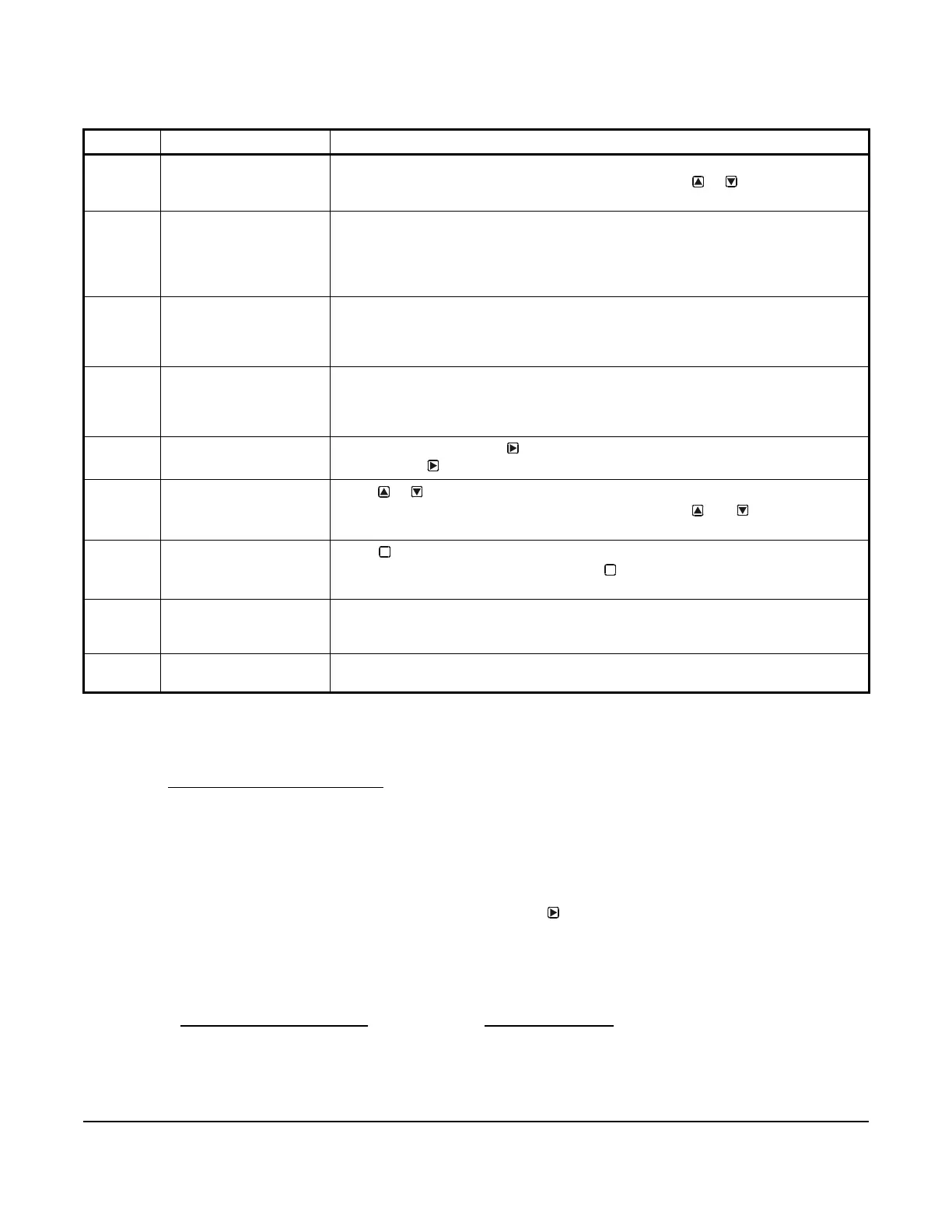
Table 2: System 450 Control Module Output Analog LEDs, LCD, Four-Button Touchpad User Interface
Callout Feature Description
1 Status or Setup Value Displays the current input status, output status, or setup parameter value for the
displayed input sensor, output, or setup parameter. Press or to select a different
parameter value when the value is flashing. (Here, 100 = 100%)
2 LED Green LEDs on Analog Control Module and Analog Expansion Modules (only)
indicate the analog output’s signal strength. When the analog output signal is
between 0 and 10 VDC, the LED blinks. The higher the output signal strength, the
longer the LED is on. The LED is off when the analog output is not generating a
signal.
3 Output Number Displays a numerical value that identifies the output associated with the status or
setup value shown on the screen. Output numbers are automatically determined by
the outputs' physical positions (left to right) in the module assembly.
(Here, 4 = Output 4)
4 Control Ramp Icon Displays whether an analog output (only) is set as direct-acting or reverse acting, and
whether the output signal strength is at minimum or maximum when the sensed
property is at Setpoint. The control ramp icon displayed is determined by the output's
SP, EP, OSP, and OEP setup values.
5 Next Button
In the Main screens, press
to scroll through the system status screens. In a setup
screen, press
to save the (flashing) setup value and go to the next setup screen.
6 Up and Down Buttons
Press or to select a different value for any flashing value in the setup value field.
In the Main (sensor status) screens, press and hold both and for 5 seconds to
access the setup Start screens.
7 Menu Button
Press to move through the sensor and output setup start screens. When moving
through the status or setup screens, press to return to the status start screen or
setup start screen.
8 Status or Setup Identifier Displays the unit of measurement, output, sensor number, or setup parameter for the
displayed status or setup value. (Here, the setup identifier OSP represents % output
signal strength at setpoint.)
9 LCD Backlit LCD screen. The LCD brightness is adjustable. During normal operation, the
LCD displays the Main screens.
M
M
 Loading...

