System 450™ Series Control Modules with Analog Outputs Installation Instructions
6
Note: Every time a module assembly is powered ON, the control module polls all of the modules to identify
output type (relay or analog) and assigns a sequential output number (1 to 9 [0 = 10]) to each output starting
with the control module output on the left. The output numbers identify each output’s setup screens in the UI.
(See Figure 4 and Table 2.)
2. Access the System 450 setup screens in the UI. See Accessing the System 450 Setup Start Screens
on page
9.
3. Set up the control system inputs or sensors in the UI. See Setting Up System 450 Sensors
on page 9.
4. Set up the control system outputs in the UI. See Setting Up System 450 Outputs
on page 15.
IMPORTANT: Do not change the module positions after a System 450 control system is set up in the UI. System
450 control logic is set up in the UI according to the Sensor Types, the output types, and the output numbers.
Changing modules or module positions in a module assembly that is already set up in the UI can change the
output numbers, output types, and the setup values of the assembly outputs, which requires setting up the
outputs again.
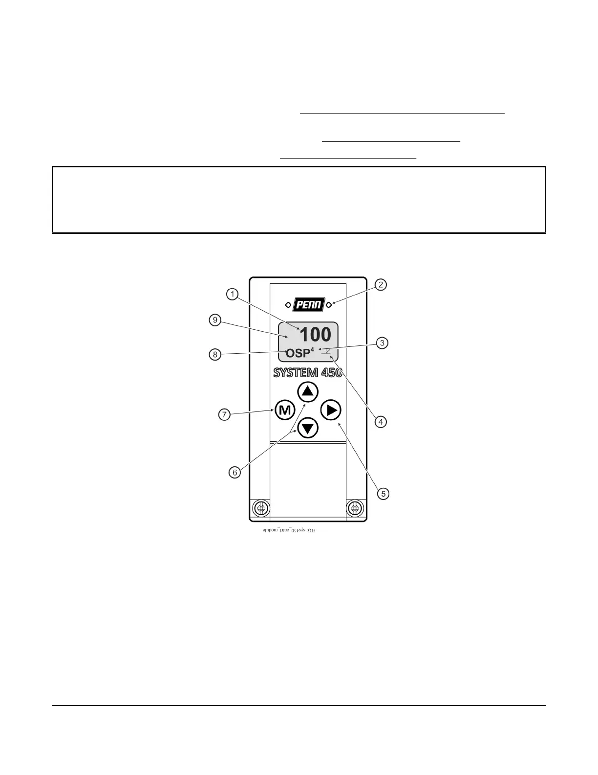
Figure 4: System 450 Control Module Output Analog LEDs, LCD, Four-Button Touchpad User Interface
 Loading...

