PENNBARRY
41
Fan Laws
The following section includes engineering and technical data,
guidelines and system explanations related to air moving
and control devices. Fan laws and system descriptions are
consistent with industry standards, defi nitions and accepted
practices. This information is provided to assist system
designers in sizing, selecting and defi ning their air moving
and control systems as well as explaining variables inherent
in system design.
There are nine fan laws, three are of prime importance to the
understanding of ventilation systems. These, together with an
appreciation of fan types, should help avoid most problems
with poor airfl ow performance. These three laws assume the
same fan operating with air at a constant density.
1. Airfl ow and fan speed are directly proportional.
CFM1 is the original fl ow rate in cu. ft. per minute.
CFM2 is the desired fl ow rate in cu. ft. per minute.
RPM1 is the original rotational speed of the fan.
RPM2 is the desired rotational speed of the fan.
2. Pressure varies as the square of the fan speed
or airfl ow.
P1 is the original static pressure.
P2 is the desired static pressure.
3. Power varies as the cube of fan speed.
=
CFM
2
CFM
1
RPM
2
RPM
1
Interaction of Fan Curves and System Curves
A ventilation system using a Breezeway may consist of a fan
with duct connected to the inlet side. Control dampers, grilles,
registers and duct fi ttings may also be part of the system.
The fan is the component in the system which provides
energy to the airstream to overcome the resistance to fl ow
off the other components. The determination of the “pressure
loss” or “resistance to fl ow”, for the individual components
can be obtained from the component manufacturers. The
determination of pressure losses for ductwork and branch
ductwork design is well documented in standard handbooks,
such as the ASHRAE Handbook of Fundamentals.
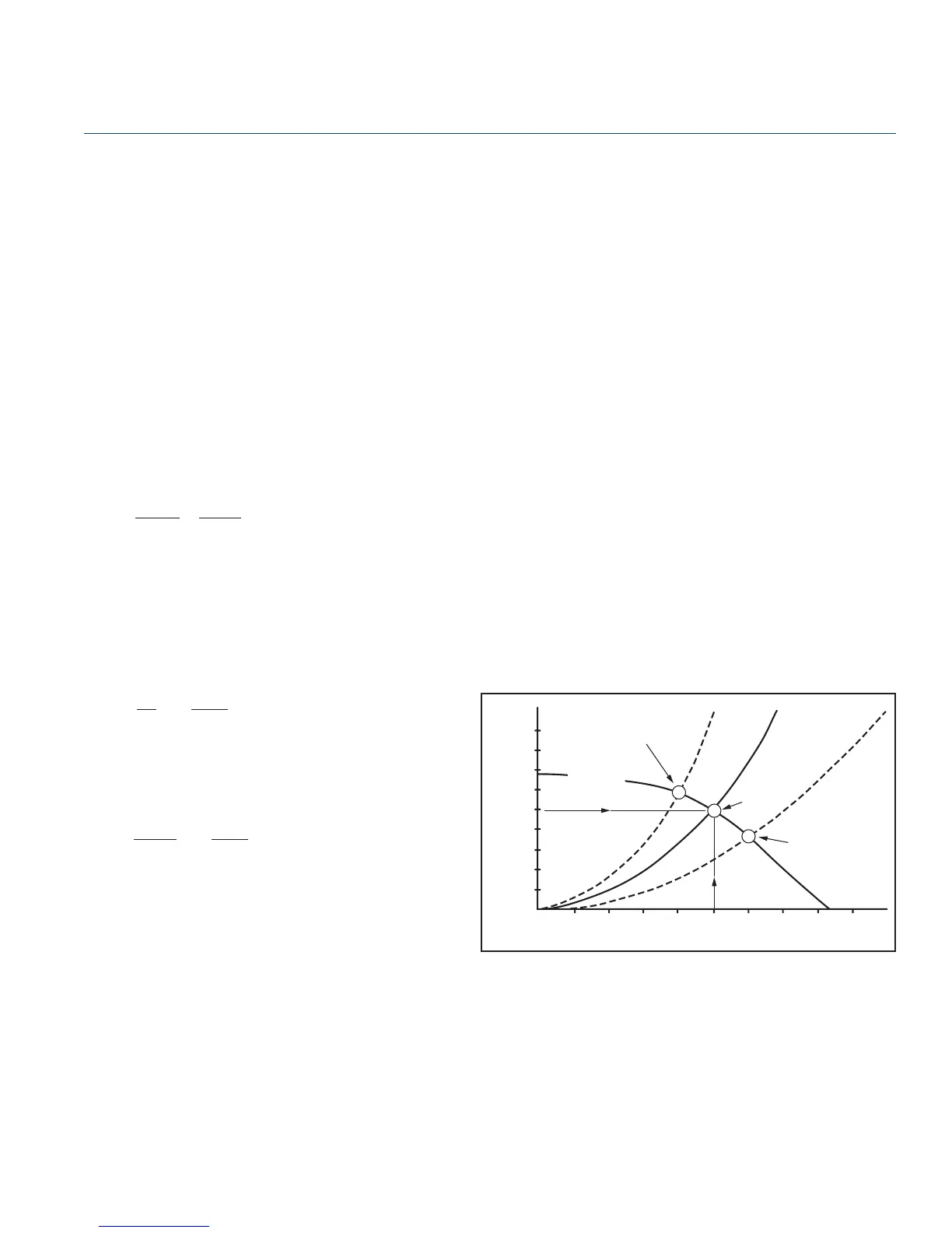
The fan curve shown in Figure 1 is a typical fan performance
curve, developed through the actual testing of a fan in an
air tunnel. The fan is run at constant speed and constant air
density. When the fan is installed in the fi eld, then it becomes
part of the system. System curves are developed by using fi eld
tested data and applying fan laws. The point of intersection of
the system curve and the fan performance curve determines
the actual fl ow volume. If the system resistance has been
accurately determined, and the fan properly selected, the
performance curves will intersect at the system design point
(point A).
P
2
RPM
1
]
RPM
2
[
2
=
P
1
BHP
2
RPM
1
]
RPM
2
[
3
=
BHP
1
Engineering Notes
Breezeway
Figure 1
Interaction of System Curves and Fan Curve
CFM
Static Pressure - Inches W.G.
B
A
C
UNDER ESTIMATED S.P.
RESULTS IN HIGH STATIC
LOW C.F.M.
FAN CURVE
DUCT SYSTEM A
SYSTEM
DESIGN
POINT
OVER ESTIMATED S.P.
RESULTS IN LOW STATIC
HIGH C.F.M.
1.500
1.375
1.125
1.000
0.875
0.750
0.625
0.500
0.375
0.125
0
200 400 600 800 1000 1200 1400 1600 1800 2000
 Loading...