PENNBARRY
43
Inlet Duct Elbows
Non-uniform fl ow into a fan inlet is the most common cause
of defi cient fan performance. An elbow located at, or in
close proximity to the fan inlet will not allow the air to enter
the impeller uniformly. The result is less than cataloged air
performance.
Inlet Vortex (Spin or Swirl)
Another major cause of reduced performance is an inlet
duct condition that produces a vortex or spin in the airstream
entering a fan inlet.
The ideal inlet condition is one which allows the air to enter
axially and uniformly without spin in either direction. A spin
in the same direction as the impeller rotation (pre-rotation)
reduces the pressure volume curve by an amount dependent
upon the intensity of the vortex. The effect is similar to the
change in the pressure volume curve achieved by inlet vanes
installed in a fan inlet; the vanes induce a controlled spin in the
direction of impeller rotation reducing the volume fl ow rate.
A counter-rotating vortex at the inlet may result in a slight
increase in the pressure-volume curve but the horsepower
will increase substantially.
Notes: 1) No bearings, drive components or electrical components shall be placed in the air or gas stream unless they are constructed or enclosed in such a manner
that failure of the component cannot ignite the surrounding gas stream.
2) The user shall electrically ground on all fan parts.
3) For this standard, non-ferrous shall be any material with less than 5% iron or any other material with demonstrated ability to be spark resistant.
4) The use of aluminum or aluminum alloys in the presence of steel which has been allowed to rust requires special consideration. Research by the
U.S.Bureau of Mines and others has shown that aluminum impellers rubbing on rusty steel may cause high-intensity sparking.
The use of the above standard in no way implies a guarantee of safety for any level of spark resistance. Spark resistant
construction does not protect against ignition of explosive gases caused by catastrophic failure or from any airstream material
that may be present in a system.
Inlet Turning Vanes
Where space limitations prevent the use of optimum fan inlet
connections, more uniform fl ow can be achieved by the use
of turning vanes in the inlet elbow.
Numerous variations of turning vanes are available from a
single curved sheet metal vane to multi-bladed “airfoil” vanes.
The pressure drop through these devices must be added to
the system pressure losses.
Spark Resistant Construction
AMCA standards offer the following defi nitions and notes
concerning spark resistant construction:
C – The fan shall be constructed so that a shift in the
impeller or shaft will not permit two ferrous parts of
the fan to rub or strike.
B – The fan shall have a non-ferrous impeller and non-
ferrous ring about the opening through which the
shaft passes. Ferrous hubs, shafts and hardware
are allowed, provided construction is such that a shift
in impeller or shaft will not permit two ferrous parts
of the fan to rub or strike. Steps must also be taken
to insure that the impeller, bearings, and shaft are
adequately attached and/or restrained to prevent a
lateral or axial shift in these components.
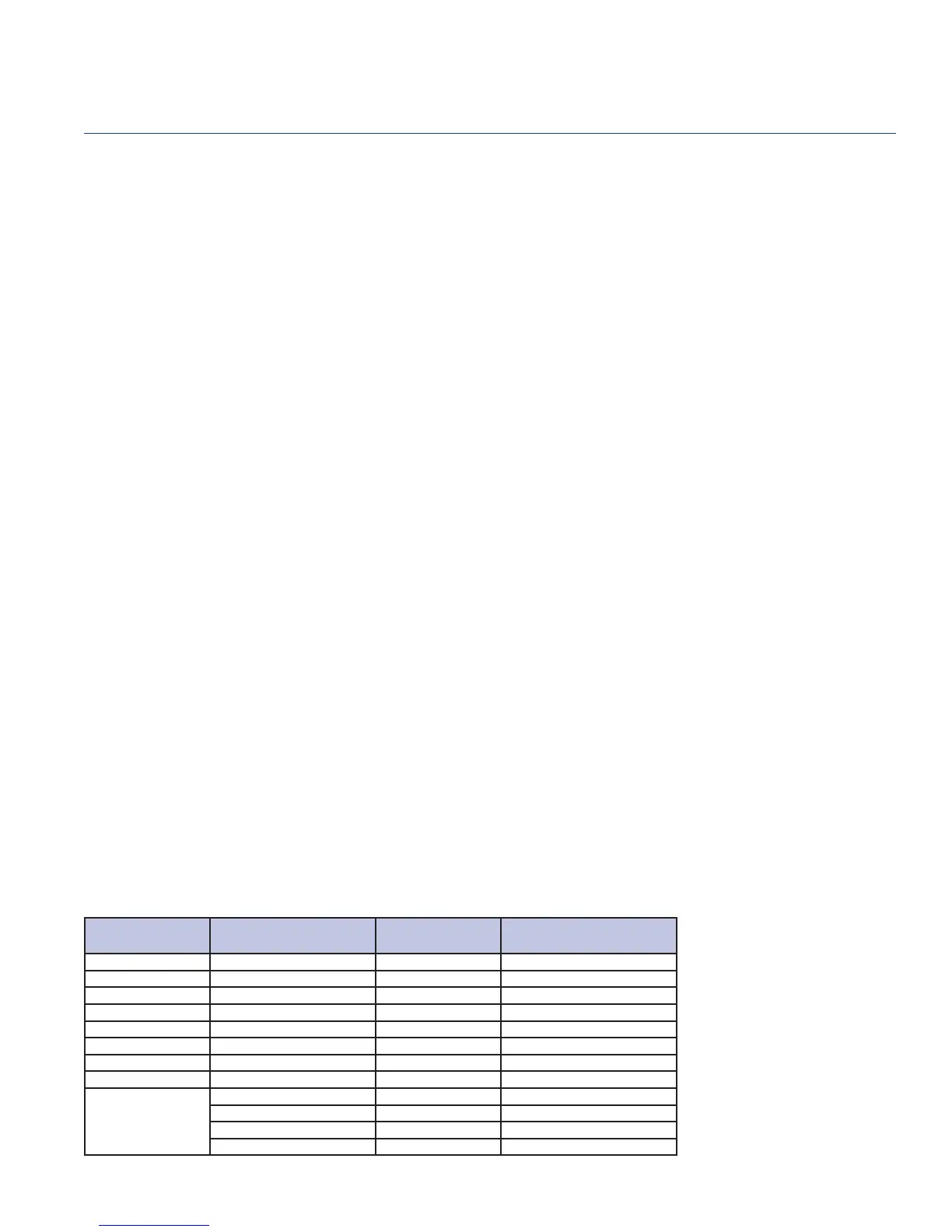
Metric Equivalents
Many PennBarry products are specifi ed and installed overseas. For your convenience,
the table below provides conversion factors from English to Metric.
CATEGORY
AMCA STANDARD /
ENGLISH UNIT
x CONVERSION
FACTOR
= METRIC (SI) UNIT
VOLUME FLOW CFM 0.00047195 cu. meter per sec. (m
3
/s)
PRESSURE Inches (wg) 248.36 pascal (Pa or N/m
2
)
POWER H.P. 745.7 watt (W or J/s)
TEMPERATURE Fahrenheit (°F) (°F + 459.67)/1.8 kelvin
HEAT Btu 1.055 kilojoules (kj)
TIP SPEED Ft/M 0.00508 meter per second (m/s)
SPEED RPM 0.016 rev. per second (rps)
VELOCITY Ft/M 0.00508 meter per second (m/s)
DIMENSIONS
Inches 25.4 millimeter (mm)
Feet 0.3048 meter (m)
Square Feet 0.0929 square meter (m
2
)
Cubic Feet 0.0283 cubic meter (m
3
)
Engineering Notes
Breezeway
 Loading...