18 / 82
EN- Raychem920series-IM-H5687405/15
INDUSTRIAL HEAT TRACING SOLUTIONS
SECTION 3 PROGRAMMING AND CONFIGURATION
3.1 INTRODUCTION
This section provides complete operating and setup instructions for the 920 Series Heat-Tracing
Controller. The text describes each available function in detail, its purpose, valid range settings,
the procedure for use, and some operational tips and suggestions.
While configuring the controller, it is important to remember that the 920 series controller is a
two control point device. Both control points allow completely independent operation and, as such,
have their own individual settings that must be configured. Throughout the text, the first control
point is referred to “Point A” and the second as “Point B.”
PROGRAMMABLE DUAL POINT
HEAT TRACING CONTROLLER
CONSOLE INTERFACE
920 SERIES
POWER
TRANSMIT
RECEIVE
ADDRESS
ALARM
“Power On” LED
indicators
Alarm status
indicators
AB
OUTPUT
A - 20910
B - 20911
Output status
indicators
Operator
console
Communications addresses
for Control Point A and
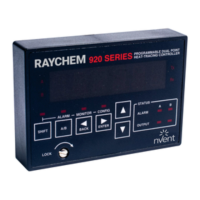
Fig 3.1 Raychem 920 front panel
3.2 FRONT PANEL FEATURES
Front panel features of the heat trace controller are shown in Figure 3.1. The remainder of this
Section describes the front panel status and display LEDs.
3.2.1 920 FRONT PANEL DISPLAY
The basic 920 series control module front panel includes seven LED indicators. Four of these are
used to indicate the “Output” and “Alarm” status of control points A and B.
Status LEDs
OUTPUT The OUTPUT LED, when illuminated steadily, indicates that the output of the controller
is turned on and is allowing current to flow in the trace circuit. For SSR versions, a flashing LED
indicates that the controller is pulsing its output on and off to maintain the setpoint temperature
and/or control the average amount of current/power the tracer uses. A separate LED is provided
for Point A and Point B.
ALARM The ALARM LEDs will flash (approximately once per second) when the controller has
detected an alarm condition. A separate LED is provided for Point A and Point B.
TRANSMIT The TRANSMIT LED (“Tx”) flashes when the controller is sending information over its
communications port to another device. This LED is only used when an optional communications
interface is installed.
RECEIVE The “RECEIVE” LED (“Rx”) flashes when the controller is receiving information
over its communications port from another device. This LED is only used when an optional
communications interface is installed.
POWER Indicates the module is powered on.
IMPORTANT: Older versions of the controller may not have this LED.
 Loading...